Isuzu KB P190. Manual - part 719
 

  Index      Isuzu     Isuzu KB P190 - service repair manual 2007 year


Search            


Content   ..  717  718  719  720   ..


Isuzu KB P190. Manual - part 719


Engine Mechanical – V6 

Page 6A1–99 


Page 6A1–99 

8 

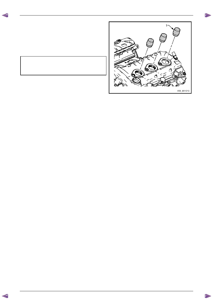
Remove Tool No. EN-46101 (1). 

9 

Tighten all remaining fasteners to the correct torque 
specification. 


Engine ground connector bolt  
torque specification ............................................10.0 Nm 

Engine wiring harness former attaching 
bolt torque specification ..........................12.0 – 16.0 Nm 


Figure 6A1 – 74 

Engine Mechanical – V6 

Page 6A1–100 


Page 6A1–100 

3.13  Crankshaft Balancer Assembly 

Remove 

1 

Remove the accessory drive belt, refer to 

3.5  Accessory Drive Belt

. 

2 

Remove the starter motor, refer to 

Section 6D1-2 Starting System

. 

3 

Install Tool No. EN-46106 (1) into the starter motor 
opening to stop the camshaft from rotating. 


Figure 6A1 – 75 

4 

Remove the bolt (1) attaching the crankshaft balancer 
assembly (2) to the crankshaft. 


Figure 6A1 – 76 

5 

Remove the crankshaft balancer assembly (1) from 
the crankshaft using the appropriate tool: 

Tool No. J-41816 (2) or equivalent. 


Figure 6A1 – 77 

Engine Mechanical – V6 

Page 6A1–101 


Page 6A1–101 

Clean and Inspect 

1 

Using a suitable non-corrosive cleaning solvent and a soft bristled parts cleaning brush, clean the crankshaft 
balancer assembly. 


Safety glasses must be worn when using 
compressed air. 

2 

Dry the crankshaft balancer assembly using compressed air. 

3 

Inspect the crankshaft balancer assembly for the following fault conditions: 
• 

Hub to crankshaft inner surface for wear or damage, 

• 

Sealing surface for wear, grooving or scoring, 

• 

Rubber ring between the hub and the pulley for wear, chunking and general deterioration, and 

• 

Drive belt ribs of the pulley for damage. 

Reinstall 

CAUTION


Do not lubricate the crankshaft front oil seal 
or crankshaft balancer sealing surfaces. The 
crankshaft balancer must be installed onto a 
dry seal. 

1 

Lubricate the crankshaft balancer assembly hub bore. 

2 

Partially install the crankshaft balancer assembly onto 
the crankshaft. 


Figure 6A1 – 78 

Engine Mechanical – V6 

Page 6A1–102 


Page 6A1–102 

3 

Using crankshaft balancer installer, Tool No.  
J-41998-B (1), fully install the crankshaft balancer 
assembly into the crankshaft. 


CAUTION


To prevent damage to the crankshaft 
threads, fully install crankshaft balancer 
installer, Tool No. J-41998-B (1) into the 
crankshaft before pressing the pulley and 
balancer assembly. 


Figure 6A1 – 79 

4 

Apply Loctite 272 or equivalent to the thread of a new 
crankshaft balancer assembly retaining bolt (1). 

5 

Install the crankshaft balancer assembly retaining bolt 
and tighten to the correct torque specification. 


„  Crankshaft balancer retaining 
bolt torque specification: 

 Stage 

1 ............90.0 – 110.0 Nm 

 Stage 

2 ...............................150

° 


Figure 6A1 – 80 


Content   ..  717  718  719  720   ..