Isuzu KB P190. Manual - part 700


  Index      Isuzu     Isuzu KB P190 - service repair manual 2007 year


Search            


Content   ..  698  699  700  701   ..


Isuzu KB P190. Manual - part 700


Engine Mechanical – V6 

Page 6A1–23 


Page 6A1–23 

Crankshaft 

The crankshaft is a forged steel design with four main bearings. The number three main bearing controls crankshaft 
thrust. A crankshaft position reluctor wheel is pressed onto the rear of the crankshaft, in front of the rear main journal. 
The crankshaft is internally balanced with an integral oil pump drive machined into the nose in front of the front main 
journal. 

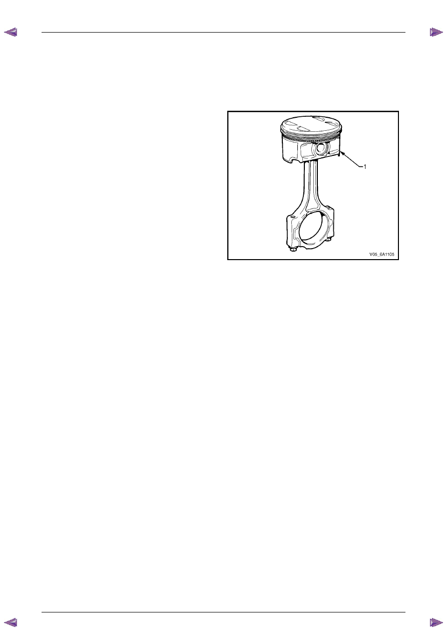
Pistons, Pins and Connecting Rods 

The piston assembly (1) is fitted with two low tension 
compression rings and one multi-piece oil control ring. The 
top compression ring is plasma sprayed, while the second 
compression ring is cast iron Napier.  

The oil control ring incorporates a steel expander and two 
chrome plated steel rails. 

The connecting rods are sinter forged steel and have full 
floating piston pins. The piston pins are a slip-fit type, into 
the bronze bushed connecting rods. Round wire retainers 
are used to retain the piston pin into the piston.  

The cast aluminium pistons incorporate a polymer coated 
skirt to reduce friction.  


Figure 6A1 – 17 

Engine Mechanical – V6 

Page 6A1–24 


Page 6A1–24 

Camshaft Drive System 

Three timing chains are fitted: 
• 

primary (1), 

• 

right-hand secondary (2), and 

• 

left-hand secondary (3), refer to Figure 6A1 – 18 for the HFV6 engine. 

The primary timing chain connects the crankshaft sprocket (4) with the left-hand and right-hand intermediate drive shaft 
sprockets (5). 

Each oil pressure fed intermediate sprocket drives the secondary timing chains, which subsequently drive the respective 
cylinder head camshaft position actuators (6). 

Two stationary timing chain guides (7) and movable timing chain shoes (8) control secondary timing chain backlash.  

Each secondary timing chain shoe is under tension from an oil pressure hydraulically operated tensioner (9). To control 
backlash on the primary chain, two stationary timing chain guides (10) and an oil pressure hydraulically actuated 
tensioner with built in shoe (11) are fitted. 

The tensioners minimise timing chain noise and provide accurate valve action by keeping slack out of the timing chains, 
while continuously adjusting for timing chain wear. The tensioners incorporate a plunger that adjusts outward with wear, 
minimising backlash. The tensioners are equipped with oiling jets to spray oil onto the timing components during engine 
operation. Each tensioner is sealed to the head or block using a rubber coated steel gasket. The gasket traps an 
adequate oil reserve to ensure quiet start-up. 


Figure 6A1 – 18 

Legend 

Primary Timing Chain 

Secondary Timing Chain, Right-hand 

Secondary Timing Chain, Left-hand 

4 Crankshaft 

Sprocket 

5 Intermediate 

Sprocket 

6 Camshaft 

Sprocket 

Secondary Timing Chain Guide  

Secondary Timing Chain Shoe 

Secondary Timing Chain Tensioner 

10 

Primary Timing Chain Guide 

11 

Primary Timing Chain Tensioner 


Engine Mechanical – V6 

Page 6A1–25 


Page 6A1–25 

1.5 

Engine Lubrication System 

Lubrication Description 

A structural diecast aluminium oil pan is fitted that incorporates an oil suction pipe, an oil deflector and an oil level 
sensor. The oil suction pipe is bolted into the oil pan and seals to the bottom of the cylinder block with a gasket. The oil 
deflector is bolted to the upper portion of the oil pan and ensures oil supply is maintained under all conditions. The oil 
level sensor is mounted through the bottom of the oil pan. 

A crankshaft driven gerotor oil pump is mounted to the front of the cylinder block. The pump, which incorporates an 
internal pressure-relief valve, draws oil from the oil suction tube through the lower passage in the cylinder block. Oil is 
then directed through an upper passage to the left-hand side of the cylinder block where the oil filter adapter is mounted. 

The oil filter adapter incorporates a top-access, cartridge style oil filter. The filter is accessed through a screw-on cap that 
incorporates an oil bypass valve. The oil filter adapter housing incorporates a drain back control valve and a threaded oil 
pressure sender. Oil flows through a lower passage within the oil filter adapter and through the oil filter cartridge. Filtered 
oil travels back through the upper passage of the adapter and into the engine block. 

Oil is then directed up and across the front of the cylinder block, through several drilled passages. These front passages 
feed oil to each cylinder head, the passage for the main bearings and piston oil jets, the right-hand and left-hand 
secondary idler sprockets and to the primary timing chain tensioner. 

Each cylinder head passage directs oil into oiling circuits for the stationary hydraulic lash adjusters (SHLAs) and the 
camshaft bearing journals.  An additional passage in the cylinder head also directs oil to the secondary timing chain 
tensioner. 

The oil passage that supplies oil to the main bearings also supplies oil to pressure actuated piston cooling oil jets. Each 
oil jet is mounted between opposing cylinder bores and directs oil to the two bores to provide extra cooling and control 
piston temperatures. 

From the front passages, oil is directed to the front of the block where the right-hand and left-hand intermediate drive 
shaft sprockets and the primary timing chain tensioner are mounted. Each camshaft timing chain tensioner relies on a 
gasket to maintain an oil reserve after the engine is turned off. All camshaft timing chain tensioners incorporate a small 
oil jet to supply an oil spray onto the camshaft timing chain components. 

Oil returns to the oil pan, either through the camshaft timing chain area or through the drain back passages on the 
outboard walls of the cylinder heads and cylinder block. 

Engine Mechanical – V6 

Page 6A1–26 


Page 6A1–26 

1.6 Service 

Notes 

Cleanliness and Care 

Throughout this Section, correct cleaning and protection of machined surfaces and friction areas is a part of the repair 
procedure. This is considered standard workshop practice, even if not specifically stated. 

When any internal engine part is serviced, care and cleanliness is extremely important. 

When components are removed for service, they should be marked, organised or retained in a specific order for 
reassembly. 

At the time of installation, components should be installed in the same location and with the same mating surface as 
when removed. 

Any engine is a combination of many machined, honed, polished and lapped surfaces with tolerances that are measured 
in thousandths of a millimetre. These surfaces should be covered or protected to avoid component damage. 

A liberal coating of clean engine oil should be applied to friction areas during assembly, as the lubrication will protect and 
lubricate friction surfaces during the initial engine start-up. 

Replacing Engine Gaskets 

Re-Using Gaskets and Applying Sealants 

• 

do not reuse any gasket unless specified, 

• 

gaskets that can be reused will be identified in the service procedure, and 

• 

do not apply sealant to any gasket or sealing surface unless specified in the service information. 

Separating Components 

• 

Use a rubber mallet to separate components. 

• 

Bump the part sideways to loosen the components. 

• 

Bumping should be done at bends or reinforced areas to prevent distortion of parts. 

Cleaning Gasket Surfaces 

• 

Where required, remove all gasket and sealing material from the part using a plastic or wood scraper. 

• 

Care must be used to avoid gouging or scraping the sealing surfaces. 

• 

Do not use any other method or technique to remove sealant or gasket material from a part. 

• 

Do not use abrasive pads, sand paper, or power tools to clean the gasket surfaces as these methods of cleaning 
can cause damage to the component sealing surfaces. Abrasive pads also produce fine grit that the oil filter cannot 
remove from the oil. This grit is abrasive and has been known to cause internal engine damage. 

Assembling Components 

• 

When assembling components, use only the sealant specified or equivalent in the service procedure. 

• 

Sealing surfaces should be clean and free of debris or oil. 

• 

Specific components such as crankshaft oil seals or valve stem oil seals may require lubrication during assembly. 

• 

Components requiring lubrication will be identified in the service procedure. 

• 

When applying sealant to a component, apply the amount specified in the service procedure. 

• 

Do not allow the sealant to enter into any blind threaded holes as it may prevent the bolt from clamping correctly or 
cause component damage when tightened. 

• 

Only ever tighten bolts to the correct torque specification. Do not over-tighten. 


Content   ..  698  699  700  701   ..