Content .. 1391 1392 1393 1394 ..
Isuzu KB P190. Manual - part 1393
8A-634 ELECTRICAL-BODY AND CHASSIS
No.
Connector face
No.
Connector face
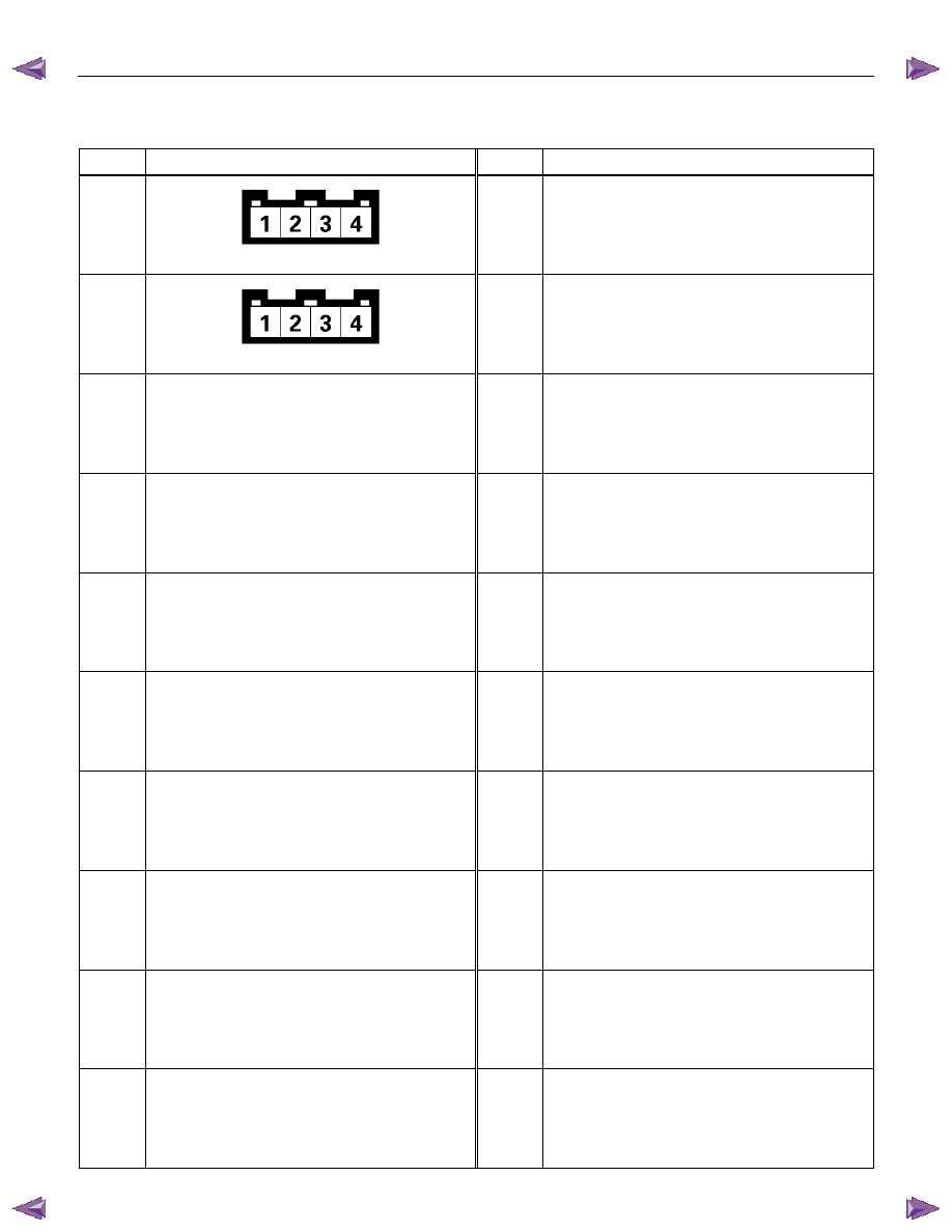
X16
Black
DIODE
X17
Black
DIODE
|
|
|
Content .. 1391 1392 1393 1394 ..
8A-634 ELECTRICAL-BODY AND CHASSIS
No. Connector face No. Connector face X16 Black DIODE
X17 Black DIODE
|