2017 Infiniti QX60/JX (2017 year). Manual - part 12


  Index      Infiniti     2017 Infiniti QX60/JX (2017 year) - manual in english


Search            copyright infringement  


Content      ..     10      11      12      13     ..


2017 Infiniti QX60/JX (2017 year). Manual - part 12


WARNING

● Always be sure the liftgate has been

closed securely to prevent it from open-
ing while driving.

● Do not drive with the liftgate open. This

could allow dangerous exhaust gases
to be drawn into the vehicle. For addi-
tional information, refer to “Exhaust
gas (carbon monoxide)” in the “Starting
and driving” section of this manual.

● To help avoid risk of injury or death

through unintended operation of the
vehicle and or its systems, including
entrapment in windows or inadvertent
door lock activation, do not leave chil-
dren, people who require the assistance
of others or pets unattended in your
vehicle. Additionally, the temperature
inside a closed vehicle on a warm day
can quickly become high enough to
cause a significant risk of injury or
death to people and pets.

● Always be sure that hands and feet are

clear of the door frame to avoid injury
while closing the liftgate.

OPERATING THE POWER LIFTGATE

WARNING

● Make sure that all passengers have

their hands, etc., inside the vehicle be-
fore closing the liftgate.

● Do not leave children unattended inside

the vehicle. They could unknowingly ac-
tivate switches or controls or make the
vehicle

move.

Unattended

children

could

become

involved

in

serious

accidents.

NOTE:

To open, close or reverse the power liftgate,
the shift lever must be in P (Park). Also, the
power liftgate will not operate if battery
voltage is low.

Power Open:
The power liftgate automatically moves from the
fully closed position to the fully open position in
approximately 5 – 8 seconds. The power open
feature can be activated by the button on the
Intelligent Key, the instrument panel switch or the
liftgate opener switch. A chime sounds to indi-
cate the power open sequence has been started.

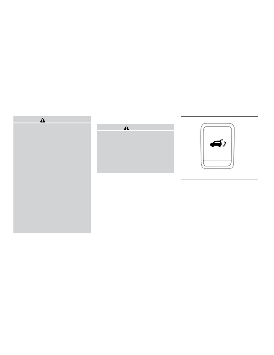
Instrument panel switch

LPD2212

LIFTGATE

3-22

Pre-driving checks and adjustments

-------------------------------------------------------------------------------------------------------------------------------------------------------------

● When the vehicle is locked, the liftgate can

be opened by the instrument panel switch,
Intelligent Key or liftgate opener switch

A

(with the Intelligent Key in liftgate range).
The liftgate will individually unlock and open.
Once the liftgate is closed, the vehicle will
remain in the unlock status.

● The Intelligent Key button must be held for

0.5 seconds before the liftgate opens.

● The liftgate must be unlocked to open it with

the liftgate opener switch

A

and without

Intelligent Key in liftgate range.

● The switch on the liftgate

A

can only be

used to open the liftgate if the MAIN switch
(located on the Instrument panel) is in the
ON position.

A warning chime will sound if the shift lever is
moved out of P (Park) during a power open
operation.

Power Close:
The power liftgate automatically moves from the
fully open position to the secondary position.
When the liftgate reaches the secondary posi-
tion, the cinching motor engages and pulls the
liftgate to its primary latch position. Power close
takes approximately 7 – 10 seconds. The power
close feature can be activated by the button on
the Intelligent Key, the instrument panel switch or
the liftgate switch

B

on the liftgate. A chime

sounds to indicate the power close sequence
has been started.

Liftgate opener switch

LPD2069

Liftgate close switch

LPD2275

Pre-driving checks and adjustments

3-23

-------------------------------------------------------------------------------------------------------------------------------------------------------------

● If the liftgate opener switch

A

is activated

while the cinching motor is engaged, the
cinching motor will disengage and release
the latch.

● The Intelligent Key button must be held for

0.5 seconds before the liftgate closes.

● The switch on the liftgate

B

can only be

used to close the liftgate if the power liftgate
main switch is in the ON position.

Stop - Reverse:
During the open/close movement, the liftgate can
be stopped if the Intelligent Key, instrument panel
or liftgate switch (

A

or

B

) is pressed. The

liftgate can be reversed if the Intelligent Key,
instrument panel or liftgate switch (

A

or

B

) is

pressed again.

Auto Reverse:
If an obstacle is detected during power open or
power close, a warning chime will sound and the
liftgate will reverse direction and return to the full
open or full close position. If a second obstacle is
detected, the liftgate motion will stop and the
liftgate will enter manual mode.

A pinch strip is mounted on each side of the
liftgate. If an obstacle is detected by a pinch strip
during power close, the liftgate will reverse direc-
tion and return to the full open position.

NOTE:

If the pinch strip is damaged or removed,
the power close function will not operate.

WARNING

There are some small distances immedi-
ately before the closed position which
cannot be detected. Make sure that all
passengers have their hands, etc., inside
the vehicle before closing the liftgate.

Manual Mode:
If power operation is not available, the liftgate
may be operated manually. Power operation may
not be available if the power liftgate main switch
is in the ON position, if multiple obstacles have
been detected in a single power cycle, or if
battery voltage is low.

If the liftgate opener switch

A

is pushed during

power open or close, the power operation will be
canceled and the liftgate can be operated manually.

To open the liftgate manually, press the liftgate
opener switch

A

and lift the liftgate.

To close, lower and push the liftgate down se-
curely.

LPD2069

3-24

Pre-driving checks and adjustments

-------------------------------------------------------------------------------------------------------------------------------------------------------------

HANDS-FREE LIFTGATE (if so
equipped)

The liftgate can be opened/closed using a foot
kicking motion when it is locked or unlocked. Two
sensors along the rear bumper (center area) can
detect a forward kicking motion

B

. The Intelli-

gent Key must be present within 3 ft (1 m) of the
liftgate to allow using the hands free feature to
open/close the liftgate.

NOTE:

To achieve proper motion activation, kick
within the kicking zone

A

2 ft (60 cm).

Improper kicking either from side to side

C

or at angles

D

will not open/close the

liftgate.

CAUTION

Before performing the kicking motion,
steady your stance to prevent any loss of
balance. Also, while making the kicking
motion, take caution around hot exhaust
system parts. Otherwise, there may be
danger of injury.

LPD2513

Example of a proper kick

LPD2484

Pre-driving checks and adjustments

3-25

-------------------------------------------------------------------------------------------------------------------------------------------------------------

While positioned at the rear of the vehicle (cen-
ter) at arms’ length distance away, begin making
the forward kicking motion. Kick the foot under
the rear bumper then immediately return the foot
back to standing position. The kicking motion
should be straight, smooth and consistent. Your
leg does not need to touch the bumper surface
but be within 3/4 inch (2 cm) to 4 inches (10 cm)
of the bumper surface. After your kick motion is
completed step back to allow the liftgate to
open/close. The liftgate should begin moving
within 1–2 seconds after the kick. This time is
needed to verify the Intelligent Key and to validate

the kick motion. Kicking again within this time
frame (1–2 seconds) could cause the liftgate to
reverse or stop.

WARNING

Prevent

unintentional

liftgate

opening/closing. There may be conditions
when opening/closing the liftgate is not
desired. Keep the Intelligent Key out of
the range of the liftgate (3 ft or 1 m), when
washing or working around the back of
the vehicle.

CAUTION

Interference or malfunction can be caused
by parking in close proximity to radio or
satellite towers.

Proper kicking zone and method

LPD2485

Improper kicking methods

LPD2486

3-26

Pre-driving checks and adjustments

-------------------------------------------------------------------------------------------------------------------------------------------------------------

POWER LIFTGATE MAIN SWITCH

The power liftgate operation can be turned on or
off by the power liftgate main switch on the
instrument panel.

When the power liftgate main switch is pushed to
the OFF position, the power operation is not
available by the power liftgate switch on the
liftgate and liftgate opener switch.

Power operation is available when in the OFF
position by the instrument panel switch and the
key fob button.

Hands-Free Liftgate (if so equipped) will not
function when the power liftgate main switch is
pushed in the OFF position.

LIFTGATE RELEASE

WARNING

● Always be sure the liftgate has been

closed securely to prevent it from open-
ing while driving.

● Do not drive with the liftgate open. This

could allow dangerous exhaust gases
to be drawn into the vehicle. For addi-
tional information, refer to “Exhaust
gas (carbon monoxide)” in the “Starting
and driving” section of this manual.

● To avoid personal injury, do not attempt

to activate the power liftgate if one or
both of the liftgate struts are removed.

CAUTION

● If the power liftgate does not stay open

or if the liftgate unexpectedly closes at
any time while a continuous warning
chime sounds, do not operate the lift-
gate. There may be a pressure loss in
one or both of the liftgate struts. It is
recommended that you have the liftgate
inspected. It is recommended that you
visit an INFINITI retailer for this service.

● Do not activate the power liftgate if one

or both of the liftgate struts are re-
moved. Damage to the liftgate or power
liftgate mechanisms may occur.

● Keep the power liftgate main switch in

the OFF position when washing or
working around the back of the vehicle
(with Intelligent Key) to prevent inad-
vertent opening/closing.

LPD2277

Pre-driving checks and adjustments

3-27

-------------------------------------------------------------------------------------------------------------------------------------------------------------

Power liftgate release

If the liftgate cannot be opened with the instru-
ment panel switch, liftgate opener switch or key
fob due to a discharged battery, follow these
steps:

1. Remove the cover

A

on the inside of the

liftgate.

2. Move the lever

B

as illustrated to open the

liftgate.

It is recommended that you visit an INFINITI re-
tailer as soon as possible for repair.

LIFTGATE POSITION SETTING

The liftgate can be set to open to a specific height
(Garage mode) by performing the following:

1. Open the liftgate using the request switch or

the Intelligent Key.

2. Pull the liftgate down and move to the de-

sired height position (the liftgate will have
some resistance when being manually ad-
justed).

3. Press and hold the power liftgate close

switch

B

located on the liftgate for more

than 3 seconds or until two beeps are heard.

The liftgate will open to the selected position
setting. To change the position of the liftgate,
repeat Steps 1-3 for setting the position of the
liftgate.

SPA2778

LPD2275

3-28

Pre-driving checks and adjustments

-------------------------------------------------------------------------------------------------------------------------------------------------------------

OPENING THE FUEL-FILLER DOOR

The fuel-filler door automatically unlocks when
the driver’s door is unlocked.

1. Unlock the fuel-filler door using one of the

following operations:

● Unlock the driver’s door with the key fob.
● Unlock the driver’s door with the key.
● Push the power door lock switch to the

unlock position.

● Push the door handle request switch

(with the key fob in range).

2. To open the fuel-filler door, push the right

side of the fuel-filler door to release.

To lock, close the fuel-filler door securely and
lock the doors.

FUEL-FILLER CAP

WARNING

● Gasoline is extremely flammable and

highly explosive under certain condi-
tions. You could be burned or seriously
injured if it is misused or mishandled.
Always stop the engine and do not
smoke or allow open flames or sparks
near the vehicle when refueling.

● Do not attempt to top off the fuel tank

after the fuel pump nozzle shuts off
automatically. Continued refueling may
cause fuel overflow, resulting in fuel
spray and possibly a fire.

● Use only an original equipment type

fuel-filler cap as a replacement. It has a
built-in safety valve needed for proper
operation of the fuel system and emis-
sion control system. An incorrect cap
can result in a serious malfunction and
possible injury. It could also cause
the

Malfunction Indicator Light

(MIL) to come on.

● Never pour fuel into the throttle body to

attempt to start your vehicle.

● Do not fill a portable fuel container in

the vehicle or trailer. Static electricity
can cause an explosion of flammable
liquid, vapor or gas in any vehicle or
trailer. To reduce the risk of serious
injury or death when filling portable fuel
containers:

– Always place the container on the

ground when filling.

– Do not use electronic devices when

filling.

– Keep the pump nozzle in contact

with the container while you are fill-
ing it.

– Use only approved portable fuel con-

tainers for flammable liquid.

CAUTION

● Do not use E-15 or E-85 fuel in your

vehicle. For additional information, re-
fer to “Fuel Recommendation” in the
“Technical and consumer information”
section of this manual.

WPD0454

FUEL-FILLER DOOR

Pre-driving checks and adjustments

3-29

-------------------------------------------------------------------------------------------------------------------------------------------------------------

● The LOOSE FUEL CAP warning will ap-

pear if the fuel-filler cap is not properly
tightened. It may take a few driving trips
for the message to be displayed. Failure
to tighten the fuel-filler cap properly
after the LOOSE FUEL CAP warning ap-
pears may cause the Malfunction Indi-
cator Light (MIL) to illuminate.

● Failure to tighten the fuel-filler cap

properly may cause the

Malfunc-

tion Indicator Light (MIL) to illuminate.
If the

light illuminates because

the fuel-filler cap is loose or missing,
tighten or install the cap and continue
to drive the vehicle. The

light

should turn off after a few driving trips.
If the

light does not turn off after a

few driving trips, have the vehicle in-
spected. It is recommended that you
visit an INFINITI retailer for this service.

● For additional information, refer to

“Malfunction Indicator Light (MIL)” in
the “Instruments and controls” section
of this manual.

● If fuel is spilled on the vehicle body,

flush it away with water to avoid paint
damage.

To remove the fuel-filler cap:

1. Turn the fuel-filler cap counterclockwise to

remove.

2. Put the fuel-filler cap on the cap holder

1

while refueling.

To install the fuel-filler cap:

1. Insert the fuel-filler cap straight into the fuel-

filler tube.

2. Turn the fuel-filler cap clockwise until a

single click is heard.

LOOSE FUEL CAP warning

The LOOSE FUEL CAP warning appears in the
vehicle information display when the fuel-filler
cap is not tightened correctly after the vehicle has
been refueled. It may take a few driving trips for
the message to be displayed. To turn off the
warning, perform the following:

1. Remove and install the fuel-filler cap as soon

as possible. For additional information, refer
to “Fuel-filler cap” in this section.

2. Tighten the fuel-filler cap until it clicks.

LPD2065

LPD2066

3-30

Pre-driving checks and adjustments

-------------------------------------------------------------------------------------------------------------------------------------------------------------

3. Press the

button

A

on the steering

wheel for about 1 second to turn off the
LOOSE FUEL CAP warning

B

after tight-

ening the fuel-filler cap.

WARNING

● Do not adjust the steering wheel while

driving. You could lose control of your
vehicle and cause an accident.

● Do not adjust the steering wheel any

closer to you than is necessary for
proper steering operation and comfort.
The driver’s air bag inflates with great
force. If you are unrestrained, leaning
forward, sitting sideways or out of posi-
tion in any way, you are at greater risk of
injury or death in a crash. You may also
receive serious or fatal injuries from the
air bag if you are up against it when it
inflates. Always sit back against the
seatback and as far away as practical
from the steering wheel. Always use the
seat belts.

TILT AND TELESCOPIC OPERATION

To adjust the steering wheel move the switch

1

in the following directions:

● Adjust the steering wheel up or down in

direction

2

to the desired tilt position.

● Adjust the steering wheel forward or back-

ward in direction

3

to the desired tele-

scopic position.

LPD2410

STEERING WHEEL

Pre-driving checks and adjustments

3-31

-------------------------------------------------------------------------------------------------------------------------------------------------------------

CAUTION

For vehicles with automatic drive posi-
tioner: Failure to reset the tilt and tele-
scoping functions of the steering wheel,
after the vehicle’s battery has been dis-
charged, may prevent the steering wheel
position from being adjusted.

For vehicles with automatic drive positioner: Both
the tilt and telescopic steering operation must be
reset after the vehicle’s battery has been dis-
charged in order to prevent the tilt and telescopic
operation from locking in one position. When the
battery has been recharged or replaced, perform
the following:

● For tilt operation: Adjust the switch

1

so

the steering wheel moves to the highest
position

2

that can be reached.

● For telescopic operation: Adjust the switch

1

so the steering wheel moves to the most

forward and backward position

3

that can

be reached.

Performing these operations resets the range of
the steering wheel’s tilt and telescopic function.

Entry/Exit function (if so equipped)

The automatic drive positioner system will make
the steering wheel move up automatically when
the driver’s door is opened and the ignition
switch is in the LOCK position. This lets the driver
get into and out of the seat more easily. The
steering wheel moves back into position when
the driver’s door is closed and the ignition switch
is pushed.

For additional information, refer to “Automatic
drive positioner” in this section.

1. To block glare from the front, swing down

the sun visor

1

.

2. To block glare from the side, remove the sun

visor from the center mount and swing the
visor to the side

2

.

WPD0435

SUN VISORS

3-32

Pre-driving checks and adjustments

-------------------------------------------------------------------------------------------------------------------------------------------------------------

3. Slide the extension

3

sun visor in or out as

needed.

CAUTION

● Do not store the sun visor before return-

ing

the

extension

to

its

original

position.

● Do not pull the extension sun visor forc-

ibly downward.

VANITY MIRRORS

To access the vanity mirror, pull the sun visor
down and flip open the mirror cover. The vanity
mirror will illuminate when the mirror cover is
open.

AUTOMATIC ANTI-GLARE
REARVIEW MIRROR

The inside mirror is designed so that it automati-
cally dims according to the intensity of the head-
lights of the vehicle following you. The automatic
anti-glare feature operates only when the ignition
switch is in the ON position.

The indicator light

2

will illuminate when the

automatic anti-glare feature is operating.

To turn off the automatic anti-glare feature, press
the

O

button. The indicator light will turn off.

LPD2067

LPD0469

MIRRORS

Pre-driving checks and adjustments

3-33

-------------------------------------------------------------------------------------------------------------------------------------------------------------

To turn on the automatic anti-glare feature, press
the

|

button again. The indicator light will turn

on.

For information on HomeLink® Universal Trans-
ceiver operation, refer to “HomeLink® Universal
Transceiver” in the “Instruments and controls”
section of this manual.

NOTE:

Do not hang any objects over the sensors

1

or apply glass cleaner to the sensors.

Doing so will reduce the sensitivity of the
sensors, resulting in improper operation.

OUTSIDE MIRRORS

The outside mirror remote control will operate
only when the ignition switch is in the ACC or ON
position.

Move the small switch

1

to select the left or right

mirror. Adjust each mirror to the desired position
using the large switch

2

.

WARNING

● Objects viewed in the outside mirror on

the passenger side are closer than they
appear. Be careful when moving to the
right. Using only this mirror could cause
an accident. Use the inside mirror or
glance over your shoulder to properly
judge distances to other objects.

● Do not adjust the mirrors while driving.

You could lose control of your vehicle
and cause an accident.

LPD2269

3-34

Pre-driving checks and adjustments

-------------------------------------------------------------------------------------------------------------------------------------------------------------

Power folding outside mirrors

CAUTION

● Do not touch the mirrors while they are

moving. Your hand may be pinched, and
the mirror may malfunction.

● Do not drive with the mirrors stored.

You will be unable to see behind the
vehicle.

Push the switch

2

to open the mirrors or the

switch

1

to close the mirrors.

If one of the mirrors are manually operated or
bumped, the mirror body can become loose at
the pivot point. To correct electronic mirror op-
eration, cycle the mirrors by pushing the switch

1

until completely closed, then push the switch

2

until the mirrors are in the open position

Reverse tilt-down feature (if so
equipped)

The reverse tilt-down feature will turn both out-
side mirror surfaces downward to provide better
rear visibility close to the vehicle when the mirror
control switch is in either the L or R position.

The mirrors automatically return to their original
position when you shift out of R (Reverse).

The outside mirror surfaces will return to their
original position when one of the following con-
ditions has occurred:

● The shift lever is moved to any position other

than R (Reverse).

● The outside mirror control switch is set to the

neutral or center position.

● The ignition switch is placed in the OFF

position.

NOTE:

If the outside mirror control switch is in the
“center” position, the mirror surface will
NOT turn downward when the shift lever is
moved to R (Reverse).

For additional information, refer to “Automatic
drive positioner” in this section.

Automatic anti-glare outside mirror (if
so equipped)

The outside mirror will automatically dim during
nighttime conditions to reduce the glare from the
headlights of trailing vehicles. The automatic anti-
glare feature operates only when the ignition
switch is placed in the ON position.

The automatic anti-glare feature will be on when
starting the vehicle. The indicator light on the
automatic anti-glare rearview mirror will illuminate
when the automatic anti-glare feature is operat-
ing.

For additional information on the automatic anti-
glare rearview mirror, refer to “Automatic anti-
glare rearview mirror” in this section.

LPD2303

Pre-driving checks and adjustments

3-35

-------------------------------------------------------------------------------------------------------------------------------------------------------------

Heated mirrors

The outside mirrors can be heated to defrost,
defog, or de-ice for improved visibility. For addi-
tional information, refer to “Rear window and
outside mirror defroster switch” in the “Instru-
ments and controls” section of this manual.

The automatic drive positioner system has two
features:

● Memory storage function
● Entry/exit function

MEMORY STORAGE FUNCTION

Two positions for the driver’s seat, steering col-
umn, and outside mirrors can be stored in the
automatic drive positioner memory. Follow these
procedures to use the memory system.

1. Place the ignition in the ON or ACC position

(the vehicle should be stopped while setting
the memory).

2. Adjust the driver’s seat, steering column,

and outside mirrors to the desired positions
by

manually

operating

each

adjusting

switch. For additional information, refer to
“Seats” in the “Safety—Seats, seat belts and
supplemental restraint system” section of

LPD2414

AUTOMATIC DRIVE POSITIONER (if
so equipped)

3-36

Pre-driving checks and adjustments

-------------------------------------------------------------------------------------------------------------------------------------------------------------

this manual, and “Steering wheel” and “Out-
side mirrors” in this section.

3. Push the SET switch and, within 5 seconds,

push the memory switch (1 or 2).

4. The indicator light for the pushed memory

switch will come ON and stay ON for ap-
proximately 5 seconds.

5. The chime will sound if the memory has been

stored.

NOTE:

If a NEW memory position is stored in the
same memory switch, the previous memory
position will be overwritten by the new
stored position.

Confirming memory storage

Push the SET switch.

● If a memory position has not been stored in

the switch (1 or 2) the indicator light for the
respective switch will come ON for approxi-
mately 0.5 seconds.

● If a memory position has been stored in the

switch (1 or 2) then the indicator light for the
respective switch will stay ON for approxi-
mately 5 seconds.

Linking a key fob to a stored memory
position

Each key fob can be linked to a stored memory
position (memory switch 1 or 2) with the follow-
ing procedure.

1. Follow steps 1-3 in the “Memory Storage

Function” section for storing the memory
position.

2. The indicator light for the pushed memory

switch will come ON. While the indicator
light is ON for 5 seconds, press the
button on the key fob. The indicator light of
the linked memory switch will blink. After the
indicator light goes off, the key fob is linked
to that memory setting.

Once it is linked, when the ignition switch is
placed in the OFF position, pressing the
button on the key fob will move the driver’s seat,
steering wheel and outside mirrors to the linked
memory switch position.

NOTE:

If a NEW memory position is stored in the
linked memory switch, then the key fob will
link the NEW position and overwrites the
previous position.

ENTRY/EXIT FUNCTION

This system is designed so that the driver’s seat
and automatic operation steering column will au-
tomatically move when the shift lever is in the P
(Park) position. This allows the driver to get into
and out of the driver’s seat more easily.

The driver’s seat will slide backward and the
steering column will move up:

● When the driver’s door is opened with the

ignition switch placed in the OFF position.

● When the ignition switch is changed from

ACC to OFF with the driver’s door open.

The driver’s seat and steering wheel will return to
the previous position:

● When the ignition switch is changed from

ACC or ON while the shift lever is in the P
(Park) position.

The entry/exit function can be adjusted or can-
celed through the vehicle settings in the vehicle
information display by performing the following:

● Switch the Exit Seat Slide from ON to OFF.
● Switch the Exit Steering UP from ON to

OFF.

Pre-driving checks and adjustments

3-37

-------------------------------------------------------------------------------------------------------------------------------------------------------------


Content      ..     10      11      12      13     ..