Infiniti Q60 Coupe (2014 year). Manual - part 7


  Index      Infiniti     Infiniti Q60 Coupe (2014 year) - manual in english


Search            copyright infringement  


Content      ..     5      6      7      8     ..


Infiniti Q60 Coupe (2014 year). Manual - part 7


2-36

Instruments and controls

SIC4192

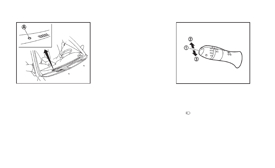
Be sure not to put anything on top of the
photo sensor

*

A

located on the top of the

instrument panel. The photo sensor con-
trols the autolight; if it is covered, the
photo sensor reacts as if it is dark and the
headlights will illuminate.

Automatic headlights off delay:

You can keep the headlights on for up to
180 seconds after you push the ignition
switch to OFF and open any door then close
all the doors.

You can adjust the period of the automatic
headlights off delay from 0 seconds (OFF)
to 180 seconds. The factory default setting
is 45 seconds.

For automatic headlights off delay setting,
see

“How to use SETTING button” (P.4-13).

SIC3269

Headlight beam select

*

1

To select the low beam, put the lever
in the neutral position as shown.

*

2

To select the high beam, push the
lever forward while the switch is in the

position. Pull it back to select the

low beam.

*

3

Pulling the lever toward you will flash
the headlight high beam even when
the headlight switch is in the OFF
position.

-------------------------------------------------------------------------------------------------------------------------------------------------------------

Battery saver system

A chime will sound when the driver side
door is opened with the light switch in the

or

position and the ignition switch

in the ACC, OFF or LOCK position.

When the headlight switch is in the

or

position while the ignition switch is in

the ON position, the lights will automati-
cally turn off after a period of time when
the ignition switch has been pushed to the
OFF position.

When the headlight switch remains in the

or

position after the lights

automatically turn off, the lights will turn
on when the ignition switch is pushed to
the ON position.

CAUTION

When you turn on the headlight switch

again after the lights automatically turn
off, the lights will not turn off auto-
matically. Be sure to turn the light
switch to the OFF position when you
leave the vehicle for extended periods of
time, otherwise the battery will be
discharged.

Never leave the light switch on when the

engine is not running for extended
periods of time even if the headlights
turn off automatically.

Daytime running light system (Ca-
nada only)

The daytime running lights automatically
illuminate when the engine is started with
the parking brake released. The daytime
running lights operate with the headlight
switch in the OFF, AUTO or

position.

Turn the headlight switch to the
position for full illumination when driving
at night.

If the parking brake is applied before the
engine is started, the daytime running
lights do not illuminate. The daytime
running lights illuminate once the parking
brake is released. The daytime running
lights will remain on until the ignition
switch is pushed to the OFF position.

SIC3257

Instruments and controls

2-37

-------------------------------------------------------------------------------------------------------------------------------------------------------------

2-38

Instruments and controls

SIC3270

Instrument brightness control

The instrument brightness control switch
can be operated when the ignition switch
is in the ON position. When the switch is
operated, the dot matrix liquid crystal
display switches to the brightness adjust-
ment mode.

Push the upper switch

*

A

to brighten the

instrument panel lights. The bar

*

1

moves

to the + side. When reaching the maximum
brightness,

“MAX” appears on the display

*

2

.

Push the lower switch

*

B

to dim the

instrument panel lights. The bar

*

1

moves

to the

− side. When reaching the minimum

brightness,

“MIN” appears on the display

*

3

. However,

“MIN” does not appear

during the nighttime.

The dot matrix liquid crystal display
returns to the normal display under the
following conditions:
. when the instrument brightness control

switch is not operated for more than 5
seconds.

. when the side or front of the

switch

or

switch on the right side of the

combination meter panel is pushed.

SIC3271

TURN SIGNAL SWITCH

*

1

Turn signal

Move the lever up or down to signal the
turning direction. When the turn is com-
pleted, the turn signals cancel automati-
cally.

*

2

Lane change signal

To indicate a lane change, move the lever
up or down to the point where lights begin
flashing.

-------------------------------------------------------------------------------------------------------------------------------------------------------------

SIC3272

FOG LIGHT SWITCH

To turn the fog lights on, turn the headlight
switch to the

position, then turn the

switch to the

position. To turn them

off, turn the switch to the OFF position.

The headlights must be on for the fog
lights to operate.

When the headlight switch is in the AUTO
position and the fog light switch is in the

position, the headlights and fog lights

turn ON at night.

SIC3312

To sound the horn, push the center pad
area of the steering wheel.

WARNING

Do not disassemble the horn. Doing so
could affect proper operation of the supple-
mental front air bag system. Tampering with
the supplemental front air bag system may
result in serious personal injury.

WARNING

Do not use or allow occupants to use the
seat heater if you or the occupants cannot
monitor elevated seat temperatures or have
an inability to feel pain in those body parts
in contact with the seat. Use of the seat
heater by such people could result in
serious injury.

CAUTION

The battery could run down if the seat

heater is operated while the engine is
not running.

Do not use the seat heater for extended

periods or when no one is using the
seat.

Do not put anything on the seat which

insulates heat, such as a blanket,
cushion, seat cover, etc. Otherwise, the
seat may become overheated.

Do not place anything hard or heavy on

the seat or pierce it with a pin or similar
object. This may result in damage to the
heater.

Instruments and controls

2-39

HORN

HEATED SEATS (if so equipped)

-------------------------------------------------------------------------------------------------------------------------------------------------------------

2-40

Instruments and controls

Any liquid spilled on the heated seat

should be removed immediately with a
dry cloth.

When cleaning the seat, never use

gasoline, thinner, or any similar materi-
als.

If any malfunctions are found or the

heated seat does not operate, turn the
switch off and have the system checked
by an INFINITI retailer.

SSS0911

The front seats are warmed by built-in
heaters. The switches located on the center
console can be operated independently of
each other.

1. Start the engine.

2. Turn the control knob

*

A

to the right

*

1

and select the desired heat range.

.

For high heat, turn the knob to the
right

*

1

.

.

For low heat, turn the knob to the left

*

2

.

.

The indicator light

*

B

will illuminate

when the heater is on.

3. To turn off the heater, return the knob

to the OFF position

*

3

. Make sure that

the indicator light turns off.

The heater is controlled by a thermis-
tor, automatically turning the heater on
and off. The indicator light will remain
on as long as the switch is on.

When the vehicle

’s interior is warmed,

or before you leave the vehicle, be sure
to turn off the switch.

-------------------------------------------------------------------------------------------------------------------------------------------------------------

SIC4040

The climate controlled seat warms up or
cools down the front seats by blowing
warm or cool air from the surface of the
seat. The switches located on the center
console can be operated independently of
each other.

The surface temperature of the climate
controlled seats is automatically controlled
at an optimum temperature. However,
adjust the temperature using the control
knob if the seats are too hot or cold.

1. Start the engine.

2. Turn the control knob

*

A

to the heat

side

*

1

or to the cool side

*

2

. The

indicator light

*

B

on the control knob

will illuminate.

3. Adjust the desired amount of the air

using the control knob

*

A

.

4. When the vehicle

’s interior is warmed

or cooled, and/or before you leave the
vehicle, be sure to turn the control
knob to the OFF position (center). The
indicator light

*

B

on the control knob

goes off at the OFF position.

To check the air filter for the climate
controlled seat, contact an INFINITI
retailer.

WARNING

Do not use or allow occupants to use the
climate controlled seats if you or the
occupants cannot monitor seat tempera-
tures or have an inability to feel pain in
those body parts in contact with the seat.
Use of the climate controlled seats by such
people could result in serious injury.

CAUTION

Do not place objects in front of the

intake inlet located behind the front

seat. Doing so could cause improper
operation or interruption of the opera-
tion.

The battery could run down if the climate

controlled seat is operated while the
engine is not running.

Do not use the climate controlled seat

for extended periods or when no one is
using the seat.

Do not put anything on the seat which

insulates heat, such as a blanket,
cushion, seat cover, etc. Otherwise, the
seat may become overheated.

Do not place anything hard or heavy on

the seat or pierce it with a pin or similar
object. This may result in damage to the
climate controlled seat.

Any liquid spilled on the seat should be

removed immediately with a dry cloth.

The climate controlled seat has air

filters. Do not operate the climate con-
trolled seat without the air filters. This
may result in damage to the system.

When cleaning the seat, never use

gasoline, thinner, or any similar materi-
als.

Instruments and controls

2-41

CLIMATE CONTROLLED SEATS (if so
equipped)

-------------------------------------------------------------------------------------------------------------------------------------------------------------

2-42

Instruments and controls

If any malfunctions are found or the

climate controlled seat does not operate,
turn the switch off and have the system
checked by an INFINITI retailer.

JVS0022X

The vehicle should be driven with the
Vehicle Dynamic Control (VDC) system on
for most driving conditions.

If the vehicle is stuck in mud or snow, the
VDC system reduces the engine output to
reduce wheel spin. The engine speed will
be reduced even if the accelerator is
depressed to the floor. If maximum engine
power is needed to free a stuck vehicle,
turn the VDC system off.

To turn off the VDC system, push the VDC
OFF switch. The

indicator will illumi-

nate.

Push the VDC OFF switch again or restart
the engine to turn on the system. (See

“Vehicle Dynamic Control (VDC) system”
(P.5-56).)

VEHICLE DYNAMIC CONTROL (VDC) OFF
SWITCH

-------------------------------------------------------------------------------------------------------------------------------------------------------------

SIC3325

If the power supply is disconnected, the
clock will not indicate the correct time.
Readjust the time.

ADJUSTING THE TIME

1. To set the clock forward, push the

button

*

1

.

2. To set the clock backward, push the

button

*

2

.

3. To move forward or backward faster,

push and hold the button more than 5
seconds.

For details about display clock adjustment
(if so equipped), see

“How to use SETTING

button

” (P.4-13).

JVI0329X

Automatic transmission models

SIC4316

Automatic transmission models

SIC4684

Manual transmission models

The power outlet is located in the center
console box and storage box (if so
equipped).

CAUTION

The outlet and plug may be hot during or

immediately after use.

Do not use with accessories that exceed

a 12 volt, 120W (10A) power draw. Do
not use double adapters or more than
one electrical accessory.

Use power outlet with the engine run-

ning to avoid discharging the vehicle

Instruments and controls

2-43

CLOCK

POWER OUTLETS

-------------------------------------------------------------------------------------------------------------------------------------------------------------

2-44

Instruments and controls

battery.

Avoid using power outlet when the air

conditioner, headlights or rear window
defroster is on.

This power outlet is not designed for use

with a cigarette lighter unit.

Push the plug in as far as it will go. If

good contact is not made, the plug may
overheat or the internal temperature
fuse may blow.

Before inserting or disconnecting a plug,

be sure the electrical accessory being
used is turned OFF.

When not in use, be sure to close the

cap. Do not allow water or any liquid to
contact the outlet.

SIC3219

FRONT

To open the ashtray lid, push the lid down
and release it

*

1

.

To empty the ashtray, pull out

*

2

.

The cigarette lighter operates when the
ignition switch is in the ON position.

Push the lighter in all the way

*

3

, then

release it. When the lighter is heated, it will
spring out. Return the lighter to its original
position after use.

CAUTION

The cigarette lighter socket is a power

source for the cigarette lighter element
only. The use of the cigarette lighter
socket as a power source for any other
accessory is not recommended.

Do not use any other power outlet for an

accessory lighter.

CIGARETTE LIGHTER AND ASHTRAYS (if so
equipped)

-------------------------------------------------------------------------------------------------------------------------------------------------------------

SIC2570

REAR

To open the ashtray lid, pull

*

1

.

To empty the ashtray, push down

*

2

, and

pull out.

CUP HOLDERS

CAUTION

Avoid abrupt starting and braking when

the cup holder is being used to prevent
spilling the drink. If the liquid is hot, it
can scald you or your passenger.

Use only soft cups in the cup holder.

Hard objects can injure you in an
accident.

SIC4689

Automatic transmission models

— Front

To open the cup holder, push the lid

*

1

.

The flap

*

A

will be folded down when

inserting a large container.

Instruments and controls

2-45

STORAGE

-------------------------------------------------------------------------------------------------------------------------------------------------------------

2-46

Instruments and controls

SIC3925

Manual transmission models

— Front

To open the cup holder, slide the lid

*

1

.

Install the partition plate into the slit

*

2

.

SIC4173

Manual transmission models

— Console

box

To open the console boxes, push the knob

*

A

and pull up the lid.

To close, push the lid down until the lock
latches.

SIC4041

Soft bottle holder

CAUTION

Do not use bottle holder for any other

objects that could be thrown about in
the vehicle and possibly injure people
during sudden braking or an accident.

Do not use bottle holder for open liquid

containers.

-------------------------------------------------------------------------------------------------------------------------------------------------------------

SIC3469

GLOVE BOX

WARNING

Keep glove box lid closed while driving to
help prevent injury in an accident or a
sudden stop.

To open the glove box, pull the handle

*

1

.

To close, push the lid in until the lock
latches.

To lock

*

2

/unlock

*

3

the glove box, use

the mechanical key. For the mechanical key
usage, see

“Keys” (P.3-3).

SIC4363

Automatic transmission models

SIC4174

Manual transmission models

CONSOLE BOX

To open the console boxes, push the knob

*

A

and pull up the lid.

To close, push the lid down until latched.

The inner tray (if so equipped) can be
moved to the front or rear position.

Instruments and controls

2-47

-------------------------------------------------------------------------------------------------------------------------------------------------------------

2-48

Instruments and controls

SIC3468

Manual transmission model

Removing the console lid (Manual
transmission model)

To remove the console lid:

1. Remove the hinge mask

*

A

using a

screwdriver wrapped with a cloth.

2. Loosen four screws, and remove the lid.

3. Tighten the two outside screws

*

B

.

4. Install the removed hinge mask

*

A

to

the original position.

SIC4308

STORAGE BOX (if so equipped)

To open, push the storage box lid

*

1

as

illustrated.

Do not use the storage box as an ashtray.

-------------------------------------------------------------------------------------------------------------------------------------------------------------

POWER WINDOWS

WARNING

Make sure that all passengers have their

hands, etc. inside the vehicle while it is
in motion and before closing the win-
dows. Use the window lock switch to
prevent unexpected use of the power
windows.

Do not leave children unattended inside

the vehicle. They could unknowingly
activate switches or controls and be-
come trapped in the window. Unat-
tended children could become involved
in serious accidents.

The power windows operate when the
ignition switch is in the ON position or for
about 45 seconds after the ignition switch
is pushed to the OFF position. If the
driver

’s or front passenger’s door is

opened during this period of about 45
seconds, power to the windows is can-
celed.

SIC3279

1.

Driver side window

2.

Front passenger side window

3.

Rear left passenger side window

4.

Rear right passenger side window

5.

Window lock button

Main power window switch (driver

’s

side)

To open or close the window, push down

*

A

or pull up

*

B

the switch and hold it.

The main switch (driver side switches) will
open or close all the windows.

Locking passengers

’ windows

When the lock button

*

C

is pushed in, only

the driver side window can be opened or
closed. Push it in again to cancel.

Instruments and controls

2-49

WINDOWS

-------------------------------------------------------------------------------------------------------------------------------------------------------------

2-50

Instruments and controls

SIC3241

Passenger side power window
switch

The passenger side switch will open or
close only the corresponding window. To
open or close the window, push down or
pull up the switch and hold it.

SIC3289

Automatic operation (for front door
windows)

To fully open or close the window, com-
pletely push down or pull up the switch
and release it; it need not be held. The
window will automatically open or close all
the way. To stop the window, just push or
lift the switch in the opposite direction.

A light push or pull on the switch will cause
the window to open or close until the
switch is released.

The rear window automatic operation is for
the opening function only.

Simultaneous operation of all four
windows

WARNING

Make sure that all passengers have their
hands, etc. inside the vehicle before closing
the windows.

When the driver

’s and passenger’s door

window switches are pushed down or
pulled up simultaneously, all four windows
are opened or closed.

Auto reverse function

WARNING

There are some small distances immediately
before the closed position which cannot be
detected. Make sure that all passengers
have their hands, etc., inside the vehicle
before closing the window.

If the control unit detects something
caught in the window as it is closing, the
window will be immediately lowered.

The auto reverse function can be activated

-------------------------------------------------------------------------------------------------------------------------------------------------------------

when the window is closed by automatic
operation when the ignition switch is in the
ON position or for 45 seconds after the
ignition switch is pushed to the OFF
position.

Depending on the environment or driving
conditions, the auto reverse function may
be activated if an impact or load similar to
something being caught in the window
occurs.

Automatic adjusting function

CAUTION

When the battery cable is removed from the
battery terminal, do not close either of the
front doors. The automatic window adjust-
ing function will not work and the side roof
panel may be damaged.

The power window has an automatic
adjusting function. When the door is being
opened, the window is automatically low-
ered slightly to avoid contact between the
window and the side roof panel. When the
door is closed, the window is automatically
raised slightly.

While the automatic adjusting function
does not work, the window will be con-
trolled as follows:
. When the door is opened, the window

lowers for approximately 0.39 in (10
mm).

. While the door is open, the window

cannot be raised.

If the windows do not close auto-
matically

If the power window automatic function
(closing only) does not operate properly,
perform the following procedure to initi-
alize the power window system.

1. Push the ignition switch to the ON

position.

2. Close the door and hard top.

3. Open the window completely by oper-

ating the power window switch.

4. Pull the power window switch and hold

it to close the window, and then hold
the switch more than 3 seconds after
the window is closed completely.

5. Release the power window switch.

Operate the window by the automatic
function to confirm the initialization is
complete.

6. Perform steps 2 through 5 above for

other windows.

If the power window automatic function
does not operate properly after performing
the procedure above, have your vehicle
checked by an INFINITI retailer.

Automatic window lowering

When the retractable hard top operating
switch is pressed, the power windows will
automatically be lowered completely. The
windows do not rise automatically after the
retractable hard top operation is com-
pleted. Use the power window switches
to raise them.

Instruments and controls

2-51

-------------------------------------------------------------------------------------------------------------------------------------------------------------


Content      ..     5      6      7      8     ..