Infiniti EX37. Transaxle and Transmission (2013 year). Manual - part 11
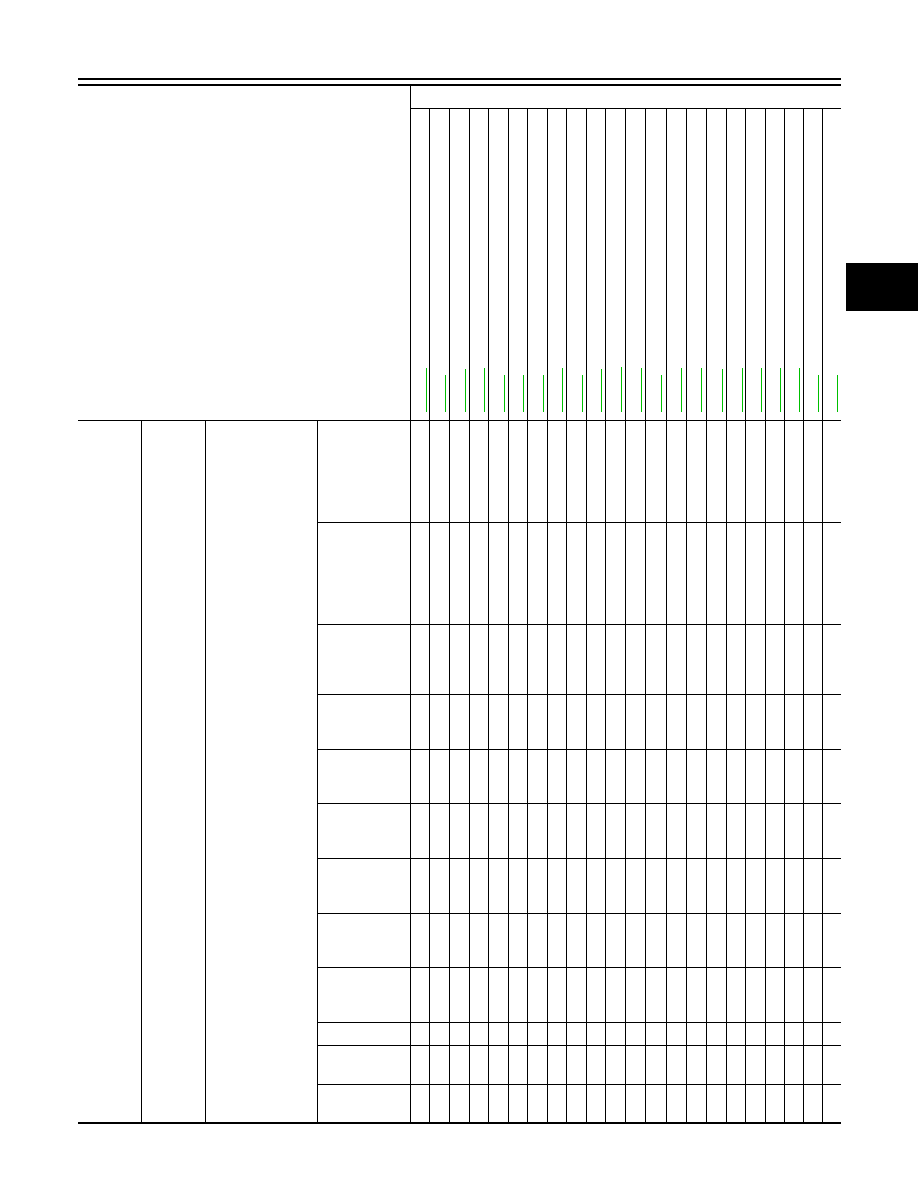
SYSTEM SYMPTOM
TM-161
< SYMPTOM DIAGNOSIS >
[7AT: RE7R01A]
C
E
F
G
H
I
J
K
L
M
A
B
TM
N
O
P
Func-
tion trou-
ble
Poor
power
trans-
mission
Slip
With selector
lever in “D”
position, ac-
celeration is
extremely
poor.
5
3
3
3
4
2
2
2
1
With selector
lever in “R”
position, ac-
celeration is
extremely
poor.
5
3
3
3
4
2
2
2
1
While starting
off by acceler-
ating in 1GR,
engine races.
3
3
3
4
2
2
2
1
While acceler-
ating in 2GR,
engine races.
3
3
3
4
2
2
2
2
1
While acceler-
ating in 3GR,
engine races.
3
3
3
4
2
2
2
2
1
While acceler-
ating in 4GR,
engine races.
3
3
3
4
2
2
2
2
1
While acceler-
ating in 5GR,
engine races.
3
3
3
4
2
2
2
2
2
1
While acceler-
ating in 6GR,
engine races.
3
3
3
4
2
2
2
2
2
1
While acceler-
ating in 7GR,
engine races.
3
3
3
4
2
2
2
2
2
1
Lock-up
3
3
3
4
2
2
1
No creep at
all.
1
1
1
1
1
1
1
1
1
Extremely
large creep.
1
Symptom
Diagnostic item
Co
nt
rol
ca
bl
e
Ou
tp
ut
sp
ee
d s
en
s
o
r
V
e
hi
cl
e s
pe
ed
s
ign
al
Acc
e
le
ra
to
r pe
da
l
p
o
s
iti
o
n
se
ns
or
En
gin
e sp
ee
d
s
ig
na
l
Inp
ut
sp
ee
d se
n
s
or
A/
T f
lui
d t
em
pe
rat
u
re se
ns
or
Ba
tte
ry vo
lt
a
g
e
T
ran
sm
is
si
o
n
ran
g
e
swi
tch
Ma
nu
al
mo
de
swi
tch
S
to
p
l
a
m
p
sw
itch
Li
n
e
pre
ss
u
re
so
le
no
id
va
lv
e
T
o
rqu
e
c
o
n
v
e
rte
r cl
utch
so
le
no
id
va
lv
e
Lo
w bra
ke
so
le
no
id
va
lv
e
F
ron
t
b
rak
e so
len
oi
d v
al
v
e
Hi
gh
an
d lo
w rev
e
rs
e cl
u
tc
h
s
o
le
n
o
id
v
a
lve
In
pu
t clu
tch
sol
eno
id
valve
Dire
ct
cl
utc
h
so
le
no
id
va
lv
e
2
346
b
rak
e s
o
len
oi
d v
al
v
e
An
ti-i
nte
rlo
ck
s
o
le
no
id
va
lv
e
S
tarter relay
CAN communication
TM-18
0
TM-80
TM-1
10
TM-10
8
TM-82
TM-78
TM-76
TM-12
4
TM-74
TM-1
16
SEC-47
TM-10
2
TM-98
TM-12
0
TM-10
7
TM-1
19
TM-10
4
TM-12
2
TM-12
1
TM-10
3
TM-72
TM-71
2013 EX