Infiniti EX37. Transaxle and Transmission (2013 year). Manual - part 10


  Index      Infiniti     Infiniti EX37. Transaxle and Transmission (2013 year) - manual in english


Search            copyright infringement  


Content      ..     8      9      10      11     ..


Infiniti EX37. Transaxle and Transmission (2013 year). Manual - part 10


TCM

TM-145

< ECU DIAGNOSIS INFORMATION >

[7AT: RE7R01A]

C

E

F

G

H

I

J

K

L

M

A

B

TM

N

O

P

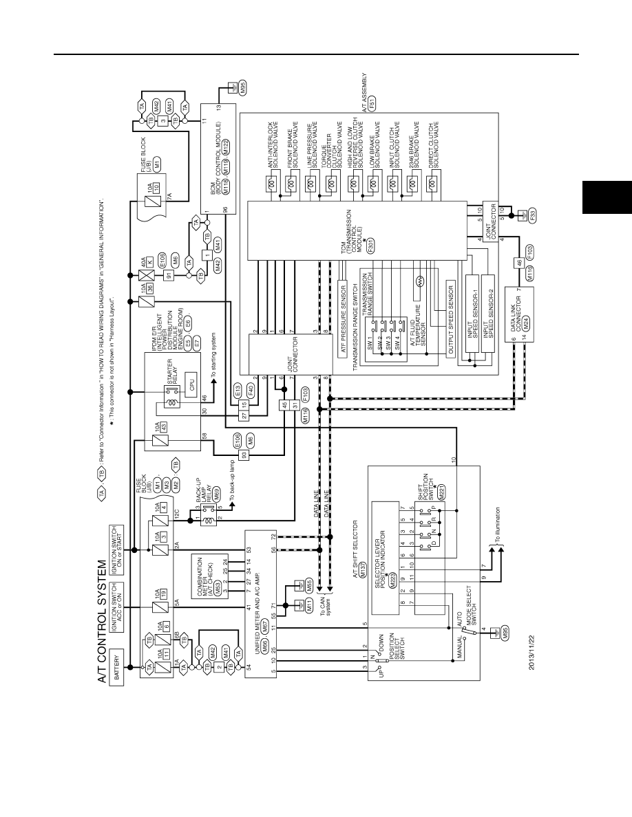
Wiring Diagram - A/T CONTROL SYSTEM -

INFOID:0000000008285876

JRDWC2201GB

2013 EX

-------------------------------------------------------------------------------------------------------------------------------------------------------------

TM-146

< ECU DIAGNOSIS INFORMATION >

[7AT: RE7R01A]

TCM

JRDWC2238GB

2013 EX

-------------------------------------------------------------------------------------------------------------------------------------------------------------

TCM

TM-147

< ECU DIAGNOSIS INFORMATION >

[7AT: RE7R01A]

C

E

F

G

H

I

J

K

L

M

A

B

TM

N

O

P

JRDWC2239GB

2013 EX

-------------------------------------------------------------------------------------------------------------------------------------------------------------

TM-148

< ECU DIAGNOSIS INFORMATION >

[7AT: RE7R01A]

TCM

JRDWC2240GB

2013 EX

-------------------------------------------------------------------------------------------------------------------------------------------------------------

TCM

TM-149

< ECU DIAGNOSIS INFORMATION >

[7AT: RE7R01A]

C

E

F

G

H

I

J

K

L

M

A

B

TM

N

O

P

JRDWC2241GB

2013 EX

-------------------------------------------------------------------------------------------------------------------------------------------------------------

TM-150

< ECU DIAGNOSIS INFORMATION >

[7AT: RE7R01A]

TCM

JRDWC2242GB

2013 EX

-------------------------------------------------------------------------------------------------------------------------------------------------------------

TCM

TM-151

< ECU DIAGNOSIS INFORMATION >

[7AT: RE7R01A]

C

E

F

G

H

I

J

K

L

M

A

B

TM

N

O

P

Fail-Safe

INFOID:0000000008285877

TCM has the electrical fail-safe mode. The mode is divided into a maximum of 3 phases (1st fail-safe, 2nd fail-
safe and final fail-safe) and functions so that the operation can be continued even if the signal circuit of the
main electronically controlled input/output parts is damaged.
Even if the electronic circuit is normal, the fail-safe mode may start under special conditions (such as when the
brake pedal is depressed suddenly from a hard wheel spin status to stop the rotation of wheels). In this case,
turn the ignition switch OFF and back to ON after 5 seconds to resume the normal shift pattern.

JRDWC2243GB

2013 EX

-------------------------------------------------------------------------------------------------------------------------------------------------------------

TM-152

< ECU DIAGNOSIS INFORMATION >

[7AT: RE7R01A]

TCM

Consequently, the customer's vehicle may already return to the normal condition. Refer to 

TM-5, "Work Flow"

.

FAIL-SAFE FUNCTION

1st fail-safe

The mode that the vehicle can stop safely, to prompt the driver to stop if the malfunction occurs and to shift to 
2nd fail-safe early. It shifts to 2nd fail-safe or final fail-safe after the vehicle stopped.

2nd fail-safe

The mode that the vehicle shifts to final fail-safe without changing the behavior, by identifying the malfunction-
ing parts in the condition that the driving force required for the driving is secured.

Final fail-safe

• Selects the shifting pattern that the malfunctioning parts identified at 1st  fail-safe and 2nd fail-safe are not 

used, and then secure the driving force that is required for the driving.

• The mode that the shifting performance does not decrease by normal shift control.

DTC

Vehicle condition

Vehicle behavior for 1st fail-

safe

Vehicle behavior for 2nd fail-

safe

Vehicle behavior for final fail-

safe

P0615

Starter is disabled

Starter is disabled

P0705

• Fixed in the “D” position 

(The shifting can be per-
formed)

• Lock-up is prohibited when 

30 km/h (19 MPH) or less

• The shifting between the 

gears of 3 - 4 - 5 - 6 - 7 can 
be performed 

• Manual mode is prohibited
• Shift position indicator is 

switched OFF

• Starter relay is switched 

OFF (starter is disabled)

• Back-up lamp is OFF
• Large shift shock

• Fixed in the “D” position 

(The shifting can be per-
formed)

• Lock-up is prohibited when 

30 km/h (19 MPH) or less

• The shifting between the 

gears of 3 - 4 - 5 - 6 - 7 can 
be performed 

• Manual mode is prohibited
• Shift position indicator is 

switched OFF

• Starter relay is switched 

OFF (starter is disabled)

• Back-up lamp is OFF
• Large shift shock

P0710

Between the gears of 1 - 2 - 3

• The shifting between the 

gears of 1 - 2 - 3 can be 
performed

• Manual mode is prohibited

• The shifting between the 

gears of 1 - 2 - 3 can be 
performed

• Manual mode is prohibited

Between the gears of 4 - 5 - 6 
- 7

• Fix the gear while driving
• Manual mode is prohibited

P0717

Between the gears of 1 - 2 - 3

• The shifting between the 

gears of 1 - 2 - 3 can be 
performed

• Manual mode is prohibited

• The shifting between the 

gears of 1 - 2 - 3 can be 
performed

• Manual mode is prohibited

Between the gears of 4 - 5 - 6 
- 7

• Fix the gear while driving
• Manual mode is prohibited

P0720

Between the gears of 1 - 2 - 3

• Only downshift can be per-

formed

• Manual mode is prohibited
• A vehicle speed signal 

from the unified meter and 
A/C amp. is regarded as 
an effective signal

• The shifting between the 

gears of 1 - 2 - 3 can be 
performed

• Manual mode is prohibited

Between the gears of 4 - 5 - 6 
- 7

• Fix the gear at driving
• Manual mode is prohibited
• A vehicle speed signal 

from the unified meter and 
A/C amp. is regarded as 
an effective signal

2013 EX

-------------------------------------------------------------------------------------------------------------------------------------------------------------

TCM

TM-153

< ECU DIAGNOSIS INFORMATION >

[7AT: RE7R01A]

C

E

F

G

H

I

J

K

L

M

A

B

TM

N

O

P

P0729
P0731
P0732
P0733
P0734
P0735
P1734

Small gear ratio difference

Engine torque limit: Max 150 
Nm

Engine torque limit: Max 150 
Nm

Great gear 
ratio differ-
ence

Neutral mal-
function be-
tween the 
gears of 1 - 2 
- 3 and 7

• Locks in 2GR, 3GR or 

4GR

• Manual mode is prohibited

• Locks  in  1GR
• The shifting between the 

gears of 1 - 2 can be per-
formed

• The shifting between the 

gears of 1 - 2 - 3 can be 
performed

• The shifting between the 

gears of 4 - 5 - 6 can be 
performed

• Manual mode is prohibited

Other than 
the above

• Locks in 1GR, 2GR, 3GR, 

4GR, 5GR or 6GR

• Fix the gear while driving
• Manual mode is prohibited

• The shifting between the 

gears of 1 - 2 - 3 can be 
performed

• Manual mode is prohibited

• Locks  in  1GR
• The shifting between the 

gears of 1 - 2 can be per-
formed

• The shifting between the 

gears of 1 - 2 - 3 can be 
performed

• The shifting between the 

gears of 2 - 3 - 4 can be 
performed

• The shifting between the 

gears of 3 - 4 can be per-
formed

• The shifting between the 

gears of 4 - 5 - 6 can be 
performed

• Manual mode is prohibited

P0730

• Locks in 5GR, 6GR or 

7GR

• Manual mode is prohibited

• The shifting between the 

gears of 1 - 2 - 3 can be 
performed

• Manual mode is prohibited

• Locks  in  1GR
• The shifting between the 

gears of 1 - 2 can be per-
formed

• The shifting between the 

gears of 1 - 2 - 3 can be 
performed

• Manual mode is prohibited

P0740

• Lock-up is prohibited
• Slip lock-up is prohibited

• Lock-up is prohibited
• Slip lock-up is prohibited

P0744

• Lock-up is prohibited
• Slip lock-up is prohibited

• Lock-up is prohibited
• Slip lock-up is prohibited

P0750
P0775
P0795
P2713
P2722
P2731
P2807

• Locks in 2GR, 3GR, 4GR, 

5GR, 6GR or 7GR

• Manual mode is prohibited

• Locks  in  1GR
• The shifting between the 

gears of 1 - 2 - 3 can be 
performed

• The shifting between the 

gears of 3 - 4 - 5 can be 
performed

• The shifting between the 

gears of 4 - 5 - 6 can be 
performed

• The shifting between the 

gears of 1 - 2 - 3 - 4 - 5 - 6 
can be performed

• Manual mode is prohibited

P0780

• Locks  in  3GR
• Manual mode is prohibited

• The shifting between the 

gears of 1 - 2 - 3 can be 
performed

• Manual mode is prohibited

DTC

Vehicle condition

Vehicle behavior for 1st fail-

safe

Vehicle behavior for 2nd fail-

safe

Vehicle behavior for final fail-

safe

2013 EX

-------------------------------------------------------------------------------------------------------------------------------------------------------------

TM-154

< ECU DIAGNOSIS INFORMATION >

[7AT: RE7R01A]

TCM

Protection Control

INFOID:0000000008285878

The TCM becomes the protection control status temporarily to protect the safety when the safety of TCM and
transmission is lost. It automatically returns to the normal status if the safety is secured.
The TCM has the following protection control.

REVERSE INHIBIT CONTROL

Intercepts the torque transmission and shift to the neutral status if the selector lever is shifted to “R” position
while the vehicle moves forward at the vehicle speed 10 km/h (7 MPH) or more.

1ST ENGINE BRAKE PROTECTION CONTROL

Controls the engine brake so as not to make effective by turning the front brake solenoid output to OFF when
each solenoid becomes the electricity pattern of 1st engine brake during driving at the vehicle speed 25 km/h
or more in any positions other than “R” position and 1GR.

P1705

• Downshift when accelera-

tor pedal is depressed is 
prohibited

• Upshift when accelerator 

pedal is released is prohib-
ited

• Manual mode is prohibited

• Downshift when accelera-

tor pedal is depressed is 
prohibited

• Upshift when accelerator 

pedal is released is prohib-
ited

• Manual mode is prohibited

• Downshift when accelera-

tor pedal is depressed is 
prohibited

• Upshift when accelerator 

pedal is released is prohib-
ited

• Manual mode is prohibited

P1730

• Locks in 1GR, 2GR, 3GR, 

4GR, 5GR, 6GR or 7GR

• Manual mode is prohibited

• The shifting between the 

gears of 1 - 2 - 3 can be 
performed

• Manual mode is prohibited

• Locks  in  1GR
• The shifting between the 

gears of 2 - 3 - 4 can be 
performed

• The shifting between the 

gears of 3 - 4 can be per-
formed

• The shifting between the 

gears of 4 - 5 - 6 can be 
performed

• Manual mode is prohibited

P1815

Manual mode is prohibited

Manual mode is prohibited

U0100
U0300
U1000

Between the gears of 1 - 2 - 3

• The shifting between the 

gears of 1 - 2 - 3 can be 
performed

• Manual mode is prohibited

• The shifting between the 

gears of 1 - 2 - 3 can be 
performed

• Line pressure is set to the 

maximum hydraulic pres-
sure

• Manual mode is prohibited

Between the gears of 4 - 5 - 6 
- 7

• Fix the gear at driving
• Manual mode is prohibited

P0720

and

P1721

Locks in 5GR

Locks in 5GR

DTC

Vehicle condition

Vehicle behavior for 1st fail-

safe

Vehicle behavior for 2nd fail-

safe

Vehicle behavior for final fail-

safe

Malfunction detection condition

Vehicle speed: 10 km/h (7 MPH) or more

Control at malfunction

Neutral

Normal return condition

• Vehicle speed: 8 km/h (5 MPH) or less

and

• Engine speed: 2,200 rpm or less

Vehicle behavior

• The torque transmission cannot be performed
• There is a shock just before a vehicle stop

Malfunction detection condition

• Select lever and gear: Any position other than “R” position and 1GR

and

• Vehicle speed: More than 25 km/h (16 MPH)

Control at malfunction

Front brake solenoid output signal; OFF

2013 EX

-------------------------------------------------------------------------------------------------------------------------------------------------------------

TCM

TM-155

< ECU DIAGNOSIS INFORMATION >

[7AT: RE7R01A]

C

E

F

G

H

I

J

K

L

M

A

B

TM

N

O

P

TCM HIGH TEMPERATURE PROTECTION CONTROL

Limit the accelerator opening and forcibly control the vehicle to the low torque driving when the electronic sub-
strate in TCM reaches the high temperature. 

DTC Inspection Priority Chart

INFOID:0000000008285879

If some DTCs are displayed at the same time, perform inspections one by one based on the priority as per the
following list.

Normal return condition

Other than detection condition of malfunction

Vehicle behavior

Does not exist

Malfunction detection condition

TCM electronic substrate temperature
• 145

°

C (293

°

F) and 120 seconds

or

• 150

°

C (302

°

F)

Control at malfunction

Accelerator opening: 0.5/8 or less

Normal return condition

• TCM electronic substrate temperature: Less than 140

°

C (284

°

F)

and

• Vehicle speed: 5 km/h (3 MPH) or less

Vehicle behavior

Accelerator opening: output torque of approximately 0.5/8

Priority

Detected items (DTC)

Reference

1

U0100 LOST COMM (ECM A)

TM-69, "DTC Logic"

U1000 CAN COMM CIRCUIT

TM-71, "DTC Logic"

2

P0615 STARTER RELAY

TM-72, "DTC Logic"

P0705 T/M RANGE SENSOR A

TM-74, "DTC Logic"

P0710 FLUID TEMP SENSOR A

TM-76, "DTC Logic"

P0717 INPUT SPEED SENSOR A

TM-78, "DTC Logic"

P0720 OUTPUT SPEED SENSOR

TM-80, "DTC Logic"

P0740 TORQUE CONVERTER

TM-98, "DTC Logic"

P0745 PC SOLENOID A

TM-102, "DTC Logic"

P0750 SHIFT SOLENOID A

TM-103, "DTC Logic"

P0775 PC SOLENOID B

TM-104, "DTC Logic"

P0795 PC SOLENOID C

TM-107, "DTC Logic"

P2713 PC SOLENOID D

TM-119, "DTC Logic"

P2722 PC SOLENOID E

TM-120, "DTC Logic"

P2731 PC SOLENOID F

TM-121, "DTC Logic"

P2807 PC SOLENOID G

TM-122, "DTC Logic"

3

P0729 6GR INCORRECT RATIO

TM-84, "DTC Logic"

P0730 INCORRECT GR RATIO

TM-86, "DTC Logic"

P0731 1GR INCORRECT RATIO

TM-88, "DTC Logic"

P0732 2GR INCORRECT RATIO

TM-90, "DTC Logic"

P0733 3GR INCORRECT RATIO

TM-92, "DTC Logic"

P0734 4GR INCORRECT RATIO

TM-94, "DTC Logic"

P0735 5GR INCORRECT RATIO

TM-96, "DTC Logic"

P0744 TORQUE CONVERTER

TM-100, "DTC Logic"

P0780 SHIFT

TM-105, "DTC Logic"

P1730 INTERLOCK

TM-112, "DTC Logic"

P1734 7GR INCORRECT RATIO

TM-114, "DTC Logic"

2013 EX

-------------------------------------------------------------------------------------------------------------------------------------------------------------

TM-156

< ECU DIAGNOSIS INFORMATION >

[7AT: RE7R01A]

TCM

DTC Index

INFOID:0000000008285880

NOTE:
• If some DTCs are displayed at the same time, perform inspections one by one based on the priority as per

the following list. Refer to 

TM-155, "DTC Inspection Priority Chart"

.

• The IGN counter is indicated in Freeze frame data (FFD). Refer to 

TM-63, "CONSULT Function"

.

4

U0300 CAN COMM DATA

TM-70, "DTC Logic"

P0725 ENGINE SPEED

TM-82, "DTC Logic"

P1705 TP SENSOR

TM-108, "DTC Logic"

P1721 VEHICLE SPEED SIGNAL

TM-110, "DTC Logic"

P1815 M-MODE SWITCH

TM-116, "DTC Logic"

Priority

Detected items (DTC)

Reference

Items

(CONSULT screen terms)

DTC

*2

Reference page

MIL

*1

, “ENGINE” with 

CONSULT or GST

CONSULT only “TRANS-

MISSION”

STARTER RELAY

P0615

TM-72, "DTC Logic"

T/M RANGE SENSOR A

P0705

P0705

TM-74, "DTC Logic"

FLUID TEMP SENSOR A

P0710

P0710

TM-76, "DTC Logic"

INPUT SPEED SENSOR A

P0717

P0717

TM-78, "DTC Logic"

OUTPUT SPEED SENSOR

P0720

P0720

TM-80, "DTC Logic"

ENGINE SPEED

P0725

TM-82, "DTC Logic"

6GR INCORRECT RATIO

P0729

P0729

TM-84, "DTC Logic"

INCORRECT GR RATIO

P0730

P0730

TM-86, "DTC Logic"

1GR INCORRECT RATIO

P0731

P0731

TM-88, "DTC Logic"

2GR INCORRECT RATIO

P0732

P0732

TM-90, "DTC Logic"

3GR INCORRECT RATIO

P0733

P0733

TM-92, "DTC Logic"

4GR INCORRECT RATIO

P0734

P0734

TM-94, "DTC Logic"

5GR INCORRECT RATIO

P0735

P0735

TM-96, "DTC Logic"

TORQUE CONVERTER

P0740

P0740

TM-98, "DTC Logic"

TORQUE CONVERTER

P0744

P0744

TM-100, "DTC Logic"

PC SOLENOID A

P0745

P0745

TM-102, "DTC Logic"

SHIFT SOLENOID A

P0750

P0750

TM-103, "DTC Logic"

PC SOLENOID B

P0775

P0775

TM-104, "DTC Logic"

SHIFT

P0780

P0780

TM-105, "DTC Logic"

PC SOLENOID C

P0795

P0795

TM-107, "DTC Logic"

TP SENSOR

P1705

TM-108, "DTC Logic"

VEHICLE SPEED SIGNAL

P1721

TM-110, "DTC Logic"

INTERLOCK

P1730

P1730

TM-112, "DTC Logic"

7GR INCORRECT RATIO

P1734

P1734

TM-114, "DTC Logic"

M-MODE SWITCH

P1815

TM-116, "DTC Logic"

PC SOLENOID D

P2713

P2713

TM-119, "DTC Logic"

PC SOLENOID E

P2722

P2722

TM-120, "DTC Logic"

PC SOLENOID F

P2731

P2731

TM-121, "DTC Logic"

PC SOLENOID G

P2807

P2807

TM-122, "DTC Logic"

LOST COMM (ECM A)

U0100

U0100

TM-69, "DTC Logic"

2013 EX

-------------------------------------------------------------------------------------------------------------------------------------------------------------

TCM

TM-157

< ECU DIAGNOSIS INFORMATION >

[7AT: RE7R01A]

C

E

F

G

H

I

J

K

L

M

A

B

TM

N

O

P

*1: Refer to 

TM-62, "Diagnosis Description"

.

*2: These numbers are prescribed by SAE J2012.

CAN COMM DATA

U0300

TM-70, "DTC Logic"

CAN COMM CIRCUIT

U1000

TM-71, "DTC Logic"

Items

(CONSULT screen terms)

DTC

*2

Reference page

MIL

*1

, “ENGINE” with 

CONSULT or GST

CONSULT only “TRANS-

MISSION”

2013 EX

-------------------------------------------------------------------------------------------------------------------------------------------------------------

TM-158

< SYMPTOM DIAGNOSIS >

[7AT: RE7R01A]

SYSTEM SYMPTOM

SYMPTOM DIAGNOSIS

SYSTEM SYMPTOM

Symptom Table

INFOID:0000000008285881

• The diagnostics item numbers show the sequence for inspection. Inspect in order from item 1.
• Perform diagnoses of symptom table 1 before symptom table 2.

SYMPTOM TABLE 1

Symptom

Diagnostic item

Control cable

Ou

tp

ut

 sp

ee

d s

en

s

o

r

V

e

h

ic

le

 sp

ee

d si

gn

al

Acc

e

le

ra

to

r pe

da

p

o

s

it

ion

 se

ns

or

En

gi

ne

 sp

ee

sig

na

l

Inp

ut

 sp

ee

d se

ns

or

A/T

 f

lu

id t

e

m

p

e

rat

ure

 se

ns

or

Ba

tte

ry vo

lt

a

g

e

T

ran

sm

is

si

on

 ran

g

e

 swi

tc

h

Ma

nu

al

 mo

de

 swi

tc

h

S

top

 la

mp

 s

w

itc

h

Li

n

e

 pre

ss

u

re

 sol

e

no

id

 va

lv

e

T

o

rq

ue

 co

nv

ert

e

r s

o

le

n

o

id

 v

a

lv

e

Lo

w bra

ke

 sol

e

no

id

 va

lv

e

F

ron

t b

rak

e so

len

oi

d va

lv

e

Hig

h

 an

d l

o

w re

ve

rse

 c

lut

ch

 s

o

le

no

id

 va

lv

e

In

pu

t clu

tch

 sol

e

n

o

id

 valve

Dire

ct

 cl

ut

ch

 so

le

no

id 

va

lv

e

23

46

 bra

k

e

 s

ol

e

no

id

 va

lv

e

An

ti-i

nte

rlo

ck

 s

o

le

no

id

 v

a

lv

e

S

tarter relay

CAN communication

TM-18

0

TM-80

TM-1

10

TM-10

8

TM-82

TM-78

TM-76

TM-12

4

TM-74

TM-1

16

SEC-47

TM-10

2

TM-98

TM-12

0

TM-10

7

TM-1

19

TM-10

4

TM-12

2

TM-12

1

TM-10

3

TM-72

TM-71

Poor 
perfor-
mance

Driving 
perfor-
mance

Shift point is high in “D” position.

1

2

3

Shift point is low in “D” position.

1

2

Large 
shock

When 
shifting 
gears


“D”  position

4

7

6

6

5

3

2

3

1

 “R” position

4

7

6

6

5

3

2

1

1GR 


2GR

4

2

5

4

4

3

1

2GR 


3GR

4

2

5

4

4

3

1

3GR 


4GR

4

2

5

4

4

3

3

1

4GR 


5GR

4

2

5

4

4

3

3

1

5GR 


6GR

4

2

5

4

4

3

3

1

6GR 


7GR

4

2

5

4

4

3

3

1

Downshift when 
accelerator ped-
al is depressed

3

2

4

3

3

1

Upshift when ac-
celerator pedal 
is released

3

2

4

3

3

1

Lock-up

4

2

4

4

4

3

1

Judder

Lock-up

2

1

1

4

3

Strange noise

In “R” position

2

1

In “N” position

2

1

In “D” position

2

1

Engine at idle

2

1

2013 EX

-------------------------------------------------------------------------------------------------------------------------------------------------------------

SYSTEM SYMPTOM

TM-159

< SYMPTOM DIAGNOSIS >

[7AT: RE7R01A]

C

E

F

G

H

I

J

K

L

M

A

B

TM

N

O

P

Symptom

Diagnostic item

Control cable

Outp

ut sp

ee

s

e

n

s

or

V

eh

icl

e sp

ee

d s

ig

na

l

Acc

e

le

ra

to

r pe

da

l p

o

s

iti

on

 se

ns

or

En

gi

ne

 sp

ee

d si

g

n

a

l

Inp

ut

 sp

ee

se

ns

or

A/T flu

id tem

p

e

rat

ure

 se

ns

or

Ba

tte

ry vo

lt

a

g

e

T

ran

sm

is

si

on

 ran

ge

 s

w

itc

h

Ma

nu

al

 mo

de

 s

w

itc

h

S

to

p

 lam

p

 swit

ch

Li

ne 

pre

s

s

u

re

 s

o

le

no

id

 va

lv

e

T

o

rqu

e

 c

o

nv

erte

r s

o

le

no

id

 va

lv

e

Lo

w bra

k

e

 s

o

le

no

id

 v

a

lv

e

Fron

b

rak

e so

le

noi

d va

lve

High

 a

n

d

 lo

w rev

e

rs

cl

utc

h

 so

len

o

id

 v

a

lv

e

Inp

ut

 cl

utc

h

 so

le

no

id 

va

lv

e

Di

re

ct cl

utch

 so

le

no

id

 va

lv

e

23

46

 bra

k

e

 s

o

leno

id

 v

a

lv

e

Ant

i-in

terl

oc

k

 so

le

noi

d va

lve

S

tarter relay

CAN communication

TM

-180

TM-80

TM-1

10

TM

-108

TM-82

TM-78

TM-76

TM

-124

TM-74

TM-1

16

SEC-47

TM

-102

TM-98

TM

-120

TM

-107

TM-1

19

TM

-104

TM

-122

TM

-121

TM

-103

TM-72

TM-71

Func-
tion 
trouble

Gear 
does no 
change

“D” position

Locks in 1GR

1

1

1

1

Locks in 2GR

Locks in 3GR

Locks in 4GR

Locks in 5GR

1

Locks in 6GR

Locks in 7GR

1GR 

 2GR

1

1

1

1

2GR 

 3GR

1

3GR 


4GR

2

2

2

2

2

2

2

1

4GR 

 5GR

1

1

5GR 

 6GR

1

6GR 

 7GR

1

1

1

1

1

5GR 

 4GR

1

4GR 

 3GR

1

1

1

3GR 

 2GR

1

1

2GR 

 1GR

1

1

1

Does  not  lock-up

2

2

2

2

4

5

3

2

2

2

2

2

2 2

2

2

1

“M” posi-
tion

1GR 


2GR

3

3

3

3

2

3

3

3

3

3

3 3

3

3

1

2GR 


3GR

3

3

3

3

2

3

3

3

3

3

3 3

3

3

1

3GR 


4GR

3

3

3

3

2

3

3

3

3

3

3 3

3

3

1

4GR 


5GR

3

3

3

3

2

3

3

3

3

3

3 3

3

3

1

5GR 


6GR

3

3

3

3

2

3

3

3

3

3

3 3

3

3

1

6GR 


7GR

3

3

3

3

2

3

3

3

3

3

3 3

3

3

1

2013 EX

-------------------------------------------------------------------------------------------------------------------------------------------------------------

TM-160

< SYMPTOM DIAGNOSIS >

[7AT: RE7R01A]

SYSTEM SYMPTOM

Symptom

Diagnostic item

Control cable

Outp

ut sp

ee

s

e

n

s

or

V

eh

icl

e sp

ee

d s

ig

na

l

Acc

e

le

ra

to

r pe

da

l p

o

s

iti

on

 se

ns

or

En

gi

ne

 sp

ee

d si

g

n

a

l

Inp

ut

 sp

ee

se

ns

or

A/T flu

id tem

p

e

rat

ure

 se

ns

or

Ba

tte

ry vo

lt

a

g

e

T

ran

sm

is

si

on

 ran

ge

 s

w

itc

h

Ma

nu

al

 mo

de

 s

w

itc

h

S

to

p

 lam

p

 swit

ch

Li

ne 

pre

s

s

u

re

 s

o

le

no

id

 va

lv

e

T

o

rqu

e

 c

o

nv

erte

r c

lut

ch

 so

le

no

id

 va

lv

e

Lo

w bra

k

e

 s

o

le

no

id

 v

a

lv

e

Fron

b

rak

e so

le

noi

d va

lve

High

 a

n

d

 lo

w rev

e

rs

cl

utc

h

 so

len

o

id

 v

a

lv

e

Inp

ut

 cl

utc

h

 so

le

no

id 

va

lv

e

Di

re

ct cl

utch

 so

le

no

id

 va

lv

e

23

46

 bra

k

e

 s

o

leno

id

 v

a

lv

e

Ant

i-in

terl

oc

k

 so

le

noi

d va

lve

S

tarter relay

CAN communication

TM

-180

TM-80

TM-1

10

TM

-108

TM-82

TM-78

TM-76

TM

-124

TM-74

TM-1

16

SEC-47

TM

-102

TM-98

TM

-120

TM

-107

TM-1

19

TM

-104

TM

-122

TM

-121

TM

-103

TM-72

TM-71

Func-
tion trou-
ble

Poor 
shifting

Slip

When 
shifting 
gears

1GR 


2GR

3

3

3

4

2

2

1

2GR 


3GR

3

3

3

4

2

2

1

3GR 


4GR

3

3

3

4

2

2

2

2

1

4GR 


5GR

3

3

3

4

2

2

2

1

5GR 


6GR

3

3

3

4

2

2

2

1

6GR 


7GR

3

3

3

4

2

2

2

1

Engine 
brake 
does 
not 
work

“D” position 

 “M” posi-

tion

5

5

5

6

4

2

3

3

3

1

“M” po-
sition

7GR 


6GR

5

5

5

6

4

2

3

3

3

1

6GR 


5GR

5

5

5

6

4

2

3

3

3

1

5GR 


4GR

5

5

5

6

4

2

3

3

3

1

4GR 


3GR

5

5

5

6

4

2

3

3

3

3

1

3GR 


2GR

5

5

5

6

4

2

3

3

3

1

2GR 


1GR

5

5

5

6

4

2

3

3

3

1

2013 EX

-------------------------------------------------------------------------------------------------------------------------------------------------------------


Content      ..     8      9      10      11     ..