Infiniti I30. Emission Control System (2003 year). Manual - part 40
SEC045DB
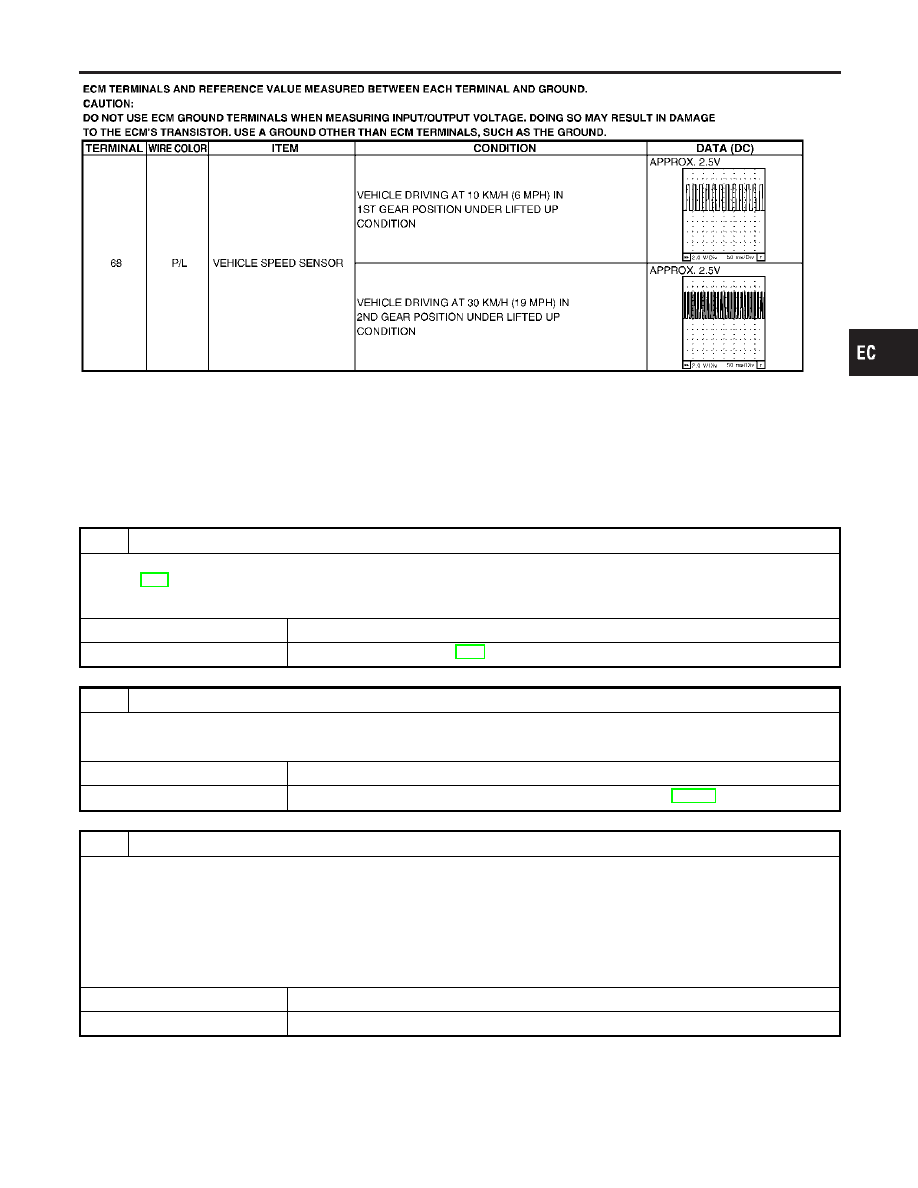
Diagnostic Procedure
NHEC1230
1
CHECK TCM FUNCTION
Check malfunction of the AT system with CONSULT-II or “O/D OFF” indicator.
Refer to AT-5.
OK or NG
OK
䊳
GO TO 2.
NG
䊳
Check AT system. Refer to AT-5.
2
CHECK SPEEDOMETER OPERATION
Check if speedometer operates normally.
OK or NG
OK
䊳
GO TO 3.
NG
䊳
Check speedometer and vehicle speed sensor circuit. Refer to EL-125.
3
CHECK VEHICLE SPEED SENSOR INPUT SIGNAL CIRCUIT FOR OPEN AND SHORT
1. Turn ignition switch “OFF”.
2. Disconnect ECM harness connector and combination meter harness connector.
3. Check harness continuity between ECM terminal 68 and combination meter terminal 32 with CONSULT-II or tester.
Refer to Wiring Diagram.
Continuity should exist.
4. Also check harness for short to ground and short to power.
OK or NG
OK
䊳
GO TO 5.
NG
䊳
GO TO 4.
GI
MA
EM
LC
FE
AT
AX
SU
BR
ST
RS
BT
HA
SC
EL
IDX
DTC P1574 ASCD VEHICLE SPEED SENSOR
Wiring Diagram (Cont’d)
EC-625