Infiniti I30. Emission Control System (2003 year). Manual - part 20
SEF332I
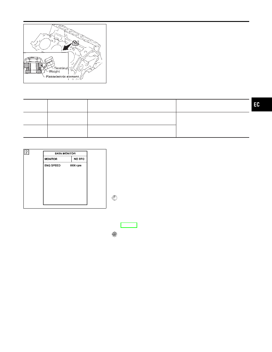
Component Description
NHEC0932
The knock sensor is attached to the cylinder block. It senses
engine knocking using a piezoelectric element. A knocking vibration
from the cylinder block is sensed as vibrational pressure. This
pressure is converted into a voltage signal and sent to the ECM.
On Board Diagnosis Logic
NHEC0934
The MIL will not light for these self-diagnoses.
DTC No.
Trouble diagnosis
name
DTC Detecting Condition
Possible Cause
P0327
0327
Knock sensor circuit
low input
An excessively low voltage from the sensor is sent
to ECM.
쐌
Harness or connectors
(The sensor circuit is open or
shorted.)
쐌
Knock sensor
P0328
0328
Knock sensor circuit
high input
An excessively high voltage from the sensor is
sent to ECM.
SEF058Y
DTC Confirmation Procedure
NHEC0935
NOTE:
If “DTC Confirmation Procedure” has been previously conducted,
always turn ignition switch “OFF” and wait at least 10 seconds
before conducting the next test.
TESTING CONDITION:
Before performing the following procedure, confirm that bat-
tery voltage is more than 10V at idle.
WITH CONSULT-II
NHEC0935S01
1)
Turn ignition switch “ON” and select “DATA MONITOR” mode
with CONSULT-II
2)
Start engine and run it for at least 5 seconds at idle speed.
3)
If 1st trip DTC is detected, go to “Diagnostic Procedure”,
EC-307.
WITH GST
NHEC0935S03
Follow the procedure “With CONSULT-II” above.
GI
MA
EM
LC
FE
AT
AX
SU
BR
ST
RS
BT
HA
SC
EL
IDX
DTC P0327, P0328 KS
Component Description
EC-305