Infiniti I30. Emission Control System (2003 year). Manual - part 5
11
PERFORM ACCELERATOR PEDAL RELEASED POSITION LEARNING
1. Stop engine.
2. Perform “Accelerator Pedal Released Position Learning”, EC-71.
䊳
GO TO 12.
12
PERFORM THROTTLE VALVE CLOSED POSITION LEARNING
Perform “Throttle Valve Closed Position Learning”, EC-71.
䊳
GO TO 13.
13
PERFORM IDLE AIR VOLUME LEARNING
Perform “Idle Air Volume Learning”, EC-71.
Is Idle Air Volume Learning carried out successfully?
Yes or No
Yes
䊳
GO TO 14.
No
䊳
1. Follow the instruction of “Idle Air Volume Learning”.
2. GO TO 4.
14
CHECK TARGET IDLE SPEED AGAIN
With CONSULT-II
1. Start engine and warm it up to normal operating temperature.
2. Read idle speed in “DATA MONITOR” mode with CONSULT-II.
675
±
50 rpm (in “P” or “N” position)
Without CONSULT-II
1. Start engine and warm it up to normal operating temperature.
2. Check idle speed.
675
±
50 rpm (in “P” or “N” position)
OK or NG
OK
䊳
GO TO 15.
NG
䊳
GO TO 17.
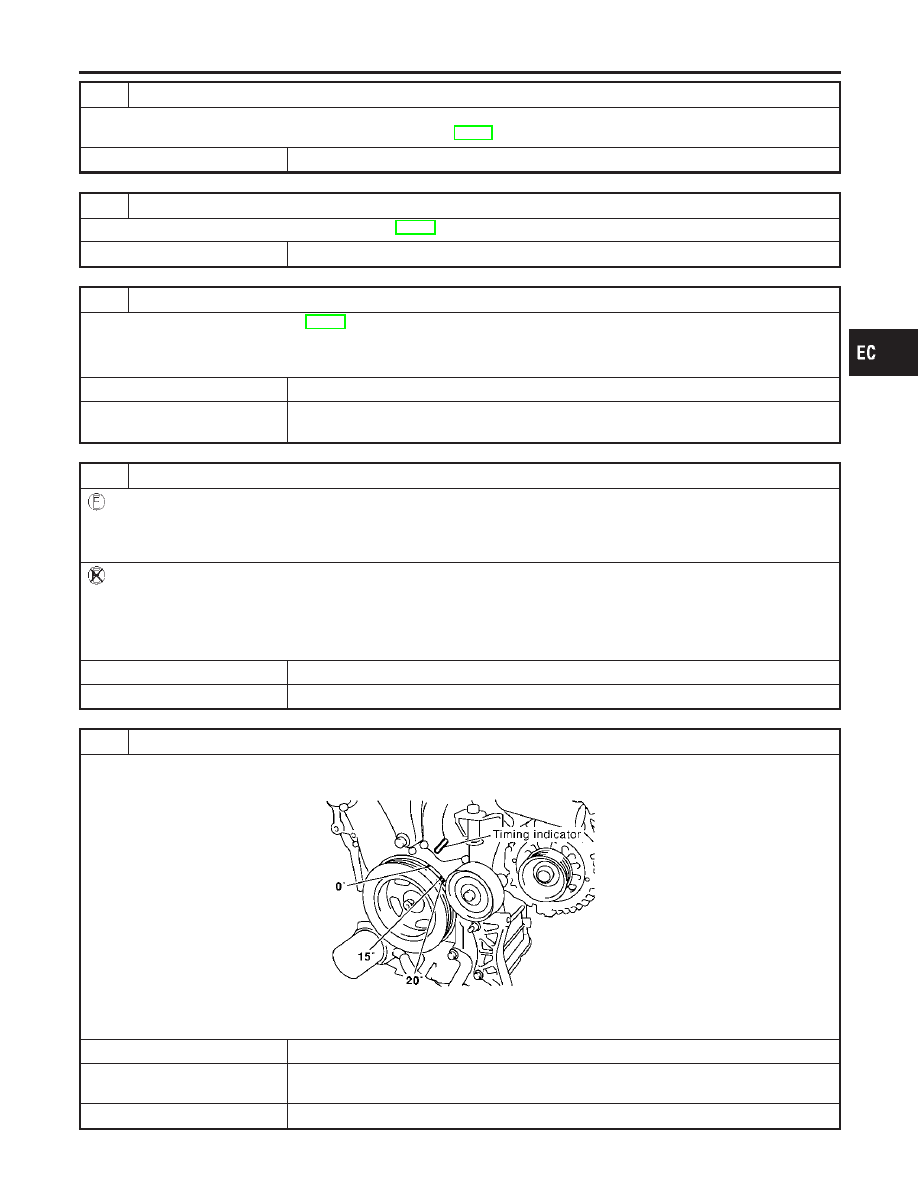
15
CHECK IGNITION TIMING AGAIN
1. Run engine at idle.
2. Check ignition timing with a timing light.
SEC004D
15°
±
5° BTDC (in “P” or “N” position)
OK or NG
OK (With CONSULT-II)
䊳
GO TO 19.
OK (Without CONSULT-
II)
䊳
GO TO 20.
NG
䊳
GO TO 16.
GI
MA
EM
LC
FE
AT
AX
SU
BR
ST
RS
BT
HA
SC
EL
IDX
BASIC SERVICE PROCEDURE
Idle Speed/Ignition Timing/Idle Mixture Ratio Adjustment (Cont’d)
EC-65