Infiniti I30. Emission Control System (2003 year). Manual - part 3
Multiport Fuel Injection (MFI) System
DESCRIPTION
NHEC0014
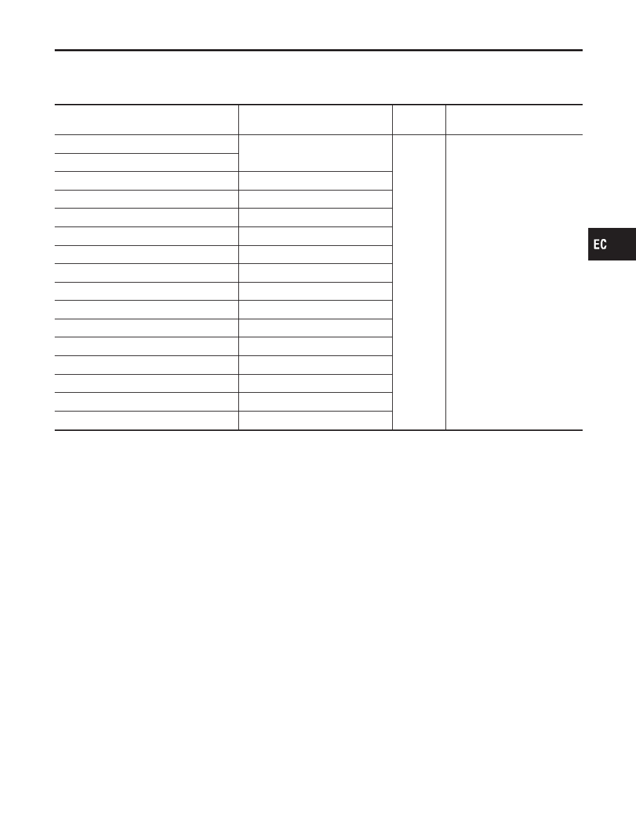
Input/Output Signal Chart
NHEC0014S01
Sensor
Input Signal to ECM
ECM func-
tion
Actuator
Crankshaft position sensor (POS)
Engine speed
Piston position
Fuel injec-
tion & mix-
ture ratio
control
Injectors
Camshaft position sensor (PHASE)
Mass air flow sensor
Amount of intake air
Engine coolant temperature sensor
Engine coolant temperature
Heated oxygen sensor 1
Density of oxygen in exhaust gas
Throttle position sensor
Throttle position
Accelerator pedal position sensor
Accelerator pedal position
Park/neutral position (PNP) switch
Gear position
Vehicle speed (From combination meter)
Vehicle speed
Ignition switch
Start signal
Air conditioner switch
Air conditioner operation
Knock sensor
Engine knocking condition
Battery
Battery voltage
Absolute pressure sensor
Ambient air barometric pressure
Power steering pressure sensor
Power steering operation
Heated oxygen sensor 2*
Density of oxygen in exhaust gas
*: This sensor is not used to control the engine system under normal conditions.
Basic Multiport Fuel Injection System
NHEC0014S02
The amount of fuel injected from the fuel injector is determined by the ECM. The ECM controls the length of
time the valve remains open (injection pulse duration). The amount of fuel injected is a program value in the
ECM memory. The program value is preset by engine operating conditions. These conditions are determined
by input signals (for engine speed and intake air) from both the crankshaft position sensor and the mass air
flow sensor.
Various Fuel Injection Increase/Decrease Compensation
NHEC0014S03
In addition, the amount of fuel injected is compensated to improve engine performance under various oper-
ating conditions as listed below.
<Fuel increase>
쐌
During warm-up
쐌
When starting the engine
쐌
During acceleration
쐌
Hot-engine operation
쐌
When selector lever is changed from “N” to “D”
쐌
High-load, high-speed operation
<Fuel decrease>
쐌
During deceleration
쐌
During high engine speed operation
GI
MA
EM
LC
FE
AT
AX
SU
BR
ST
RS
BT
HA
SC
EL
IDX
ENGINE AND EMISSION BASIC CONTROL SYSTEM DESCRIPTION
Multiport Fuel Injection (MFI) System
EC-33