Infiniti I30. Emission Control System (2003 year). Manual - part 2
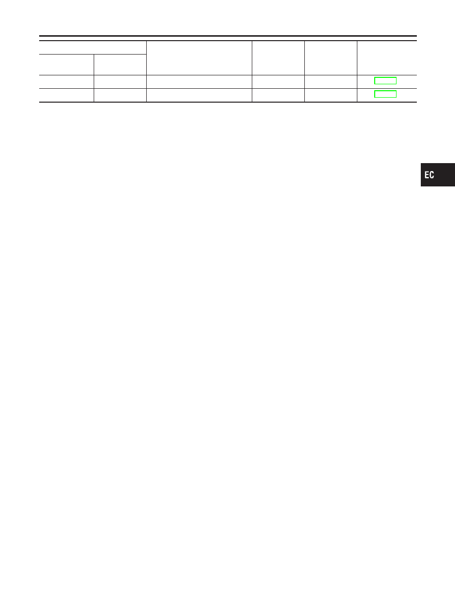
DTC*1
Items (CONSULT-II screen terms)
Trip
MIL lighting up
Reference page
CONSULT-II
GST*2
ECM*3
P2135
2135
TP SENSOR
1
X
P2138
2138
APP SENSOR
1
X
*1: 1st trip DTC No. is the same as DTC No.
*2: This number is prescribed by SAE J2012.
*3: In Diagnostic Test Mode II (Self-diagnostic results), these numbers are controlled by NISSAN.
*4: When engine is running.
*5: The troubleshooting for this DTC needs CONSULT-II.
*6: When fail-safe operations for both self-diagnoses occur at the same time, the MIL illuminates.
GI
MA
EM
LC
FE
AT
AX
SU
BR
ST
RS
BT
HA
SC
EL
IDX
TROUBLE DIAGNOSIS — INDEX
DTC No. Index (Cont’d)
EC-17