Infiniti QX56 (JA60). Manual - part 683


  Index      Infiniti     Infiniti QX56 (JA60) - service repair manual 2010 year


Search            


Content   ..  681  682  683  684   ..


Infiniti QX56 (JA60). Manual - part 683


ENGINE MAINTENANCE

MA-25

< ON-VEHICLE MAINTENANCE >

C

D

E

F

G

H

I

J

K

L

M

B

MA

N

O

A

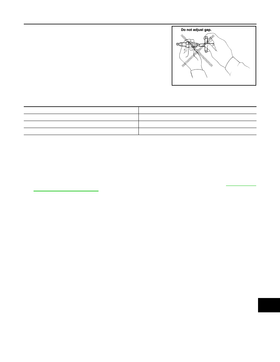
• Checking and adjusting plug gap is not required between change

intervals.

INSTALLATION

Installation is in the reverse order of removal.

Spark Plug Types

CAUTION:

Do not drop or shock spark plug.

EVAP VAPOR LINES
EVAP VAPOR LINES : Checking EVAP Vapor Line

INFOID:0000000005259660

1. Visually inspect the EVAP vapor lines for improper attachment, cracks, damage, loose connections, chaf-

ing, or deterioration.

2. Inspect the vacuum relief valve of the fuel tank filler cap for clogging and sticking. Refer to 

EC-491, "How

to Detect Fuel Vapor Leakage"

 .

SMA806CA

Make

NGK

Model

Standard model

Standard type

DILFR5A-11

Gap (Nominal)

1.1 mm (0.043 in)

MA-26

< ON-VEHICLE MAINTENANCE >

CHASSIS AND BODY MAINTENANCE

CHASSIS AND BODY MAINTENANCE

IN-CABIN MICROFILTER
IN-CABIN MICROFILTER : Removal and Installation

INFOID:0000000005403149

REPLACEMENT PROCEDURE

1. Remove the glove box assembly from the instrument panel. Refer to 

IP-17, "Removal and Installation"

.

2. Remove the screw and remove the in-cabin microfilter cover as

shown.

3. Remove the two in-cabin microfilters from the front heater and

cooling unit assembly housing.

4. Insert the first new in-cabin microfilter into the front heater and

cooling unit assembly housing and slide it over to the right.

Insert the second new in-cabin microfilter into the front heater

and cooling unit assembly housing as shown.

NOTE:

The in-cabin microfilters are marked with air flow arrows. The

end of the microfilter with the arrow should face the rear of the

vehicle. The arrows should point downward.

5. Install the in-cabin microfilter cover.

6. Install the glove box assembly in the instrument panel. Refer to 

IP-17, "Removal and Installation"

.

7. Fill out the date information on the small replacement label and attach it to the glove box lid.

EXHAUST SYSTEM
EXHAUST SYSTEM : Checking Exhaust System

INFOID:0000000005403150

Check exhaust pipes, muffler and mounting for improper attachment, leaks, cracks, damage or deterioration.

LJIA0134E

LJIA0148E

LJIA0134E

CHASSIS AND BODY MAINTENANCE

MA-27

< ON-VEHICLE MAINTENANCE >

C

D

E

F

G

H

I

J

K

L

M

B

MA

N

O

A

• If anything is found, repair or replace damaged parts.

A/T FLUID
A/T FLUID : Checking the A/T Fluid (ATF)

INFOID:0000000005403151

CAUTION:

If using the vehicle for towing, the A/T fluid must be replaced as specified. Refer to 

MA-9, "Introduc-

tion of Periodic Maintenance"

.

1. Before driving, the A/T fluid level can be checked at A/T fluid

temperatures of 30

° to 50° C (86° to 122° F) using the “COLD”

range on the A/T fluid level gauge as follows:

a. Park the vehicle on a level surface and set the parking brake.
b. Start the engine and move the selector lever through each gear

position. Shift the selector lever into the “P” position.

c. Check the A/T fluid level with the engine idling.
d. Remove the A/T fluid level gauge and wipe it clean with a lint-

free paper.

CAUTION:

When wiping the A/T fluid from the A/T fluid level gauge,

always use a lint-free paper, not a cloth.

e. Re-insert the A/T fluid level gauge into the A/T fluid charging

pipe until the cap contacts the top of the A/T fluid charging pipe

as shown.

CAUTION:

To check A/T fluid level, insert the A/T fluid level gauge until

the cap contacts the top of the A/T fluid charging pipe, with

the gauge reversed from the normal inserted position.

f.

Remove the A/T fluid level gauge and note the A/T fluid level. If

the A/T fluid level is at low side of range, add A/T fluid to the

transmission through the A/T fluid charging pipe.

CAUTION:

Do not overfill the transmission with A/T fluid.

g. Install the A/T fluid level gauge and the A/T fluid level gauge bolt.

2. Warm up the engine and transmission.
3. Check for any A/T fluid leaks.
4. Drive the vehicle to increase the A/T fluid temperature to 80

° C (176° F).

SMA211A

LLIA0071E

A/T fluid level 
gauge bolt

: Refer to 

TM-186, "Removal and Installation (2WD)"

 or 

TM-188, "Removal 

and Installation (4WD)"

SCIA2899E

MA-28

< ON-VEHICLE MAINTENANCE >

CHASSIS AND BODY MAINTENANCE

5. Allow the A/T fluid temperature to fall to approximately 65

°C (149°F). Use the CONSULT-III to monitor the

A/T fluid temperature as follows:

NOTE:

The A/T fluid level will be significantly affected by the A/T fluid temperature as shown. Therefore monitor

the A/T fluid temperature data using the CONSULT-III.

a. Connect CONSULT-III to data link connector.
b. Select “MAIN SIGNALS” in “DATA MONITOR” mode for “A/T” with CONSULT-III.
c.

Read out the value of “ATF TEMP 1”.

6. Re-check the A/T fluid level at A/T fluid temperatures of approxi-

mately 65

°C (149°F) using the “HOT” range on the A/T fluid

level gauge as shown. The HOT range is between 50

° - 80° C

(122

° - 176° F).

CAUTION:

• When wiping the A/T fluid from the A/T fluid level gauge,

always use lint-free paper, not a cloth.

• To check the A/T fluid level, insert the A/T fluid level

gauge until the cap contacts the top of the A/T fluid charg-

ing pipe, with the gauge reversed from the normal

inserted position as shown.

7. Check the A/T fluid condition.

• If the A/T fluid is very dark or has some burned smell, there

may be an internal problem with the transmission. Refer to

TM-152, "A/T Fluid Cooler Cleaning"

. Flush the transmission

cooling system after repairing the transmission.

• If the A/T fluid contains frictional material (clutches, bands,

etc.), replace the radiator and flush the transmission cooler

lines using cleaning solvent and compressed air after repairing

the transmission.

8. Install the A/T fluid level gauge in the A/T fluid charging pipe.
9. Tighten the A/T fluid level gauge bolt to specification.

SLIA0016E

LLIA0071E

A/T fluid level 
gauge bolt

: Refer to 

TM-186, "Removal and Installation (2WD)"

 or 

TM-188, "Removal 

and Installation (4WD)"

SCIA2899E


Content   ..  681  682  683  684   ..