Infiniti QX56 (JA60). Manual - part 649
IP-20
< ON-VEHICLE REPAIR >
FRONT CENTER CONSOLE
FRONT CENTER CONSOLE
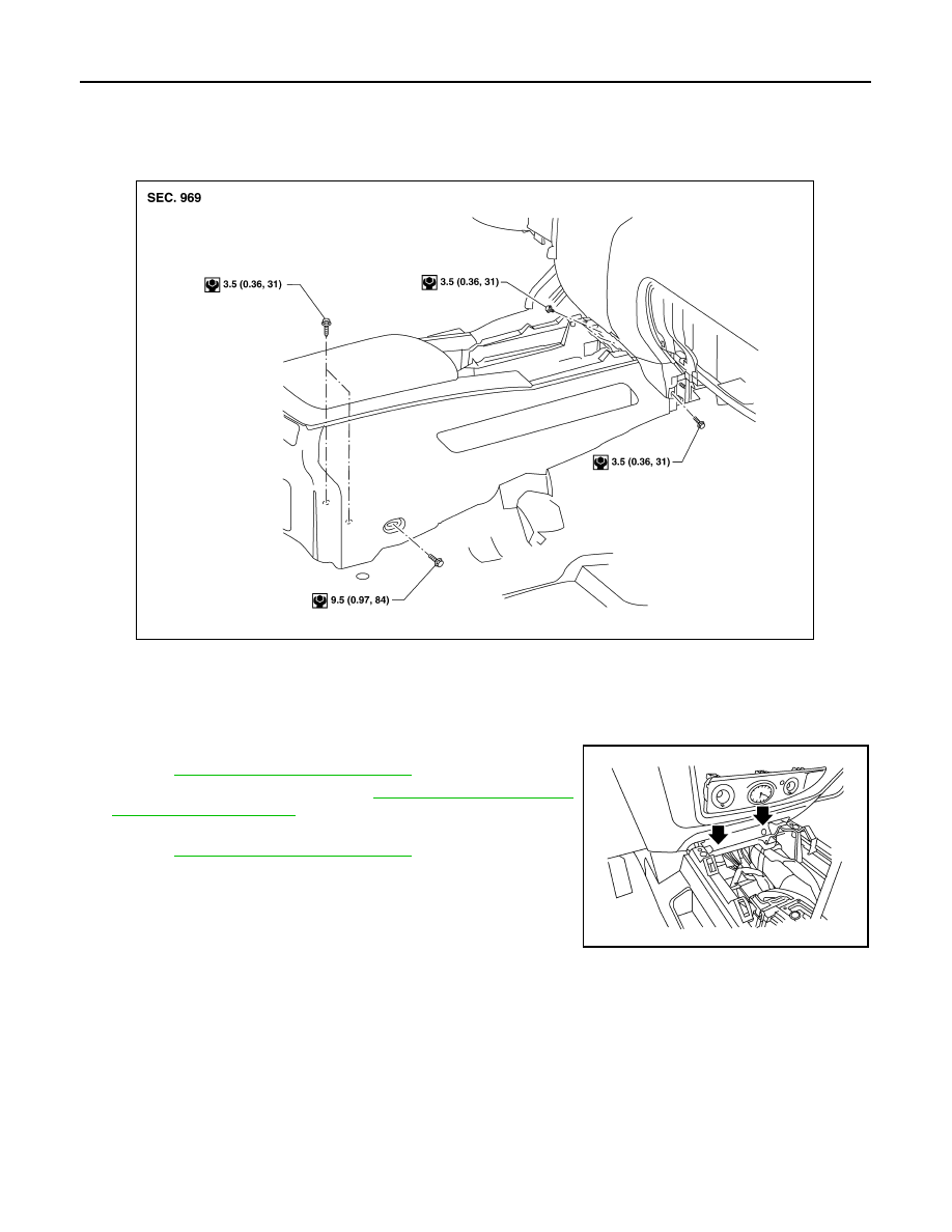
Exploded View
INFOID:0000000005147372
Removal and Installation
INFOID:0000000005147373
REMOVAL
1. Move front seats forward.
2. Remove A/T finisher and front center console upper screws.
IP-19, "Removal and Installation"
.
3. Remove A/T shift selector. Refer to
.
4. Remove instrument lower panel RH and glove box assembly.
IP-17, "Removal and Installation"
.
5. Remove center console lower cover RH/LH, then remove front
center console lower screws.
6. Open the console lid assembly and remove console bin mat,
then remove the rear inside screws.
7. Remove lower front center console screws at the rear.
8. Release front center console from floor and tilt to disconnect electrical connectors.
9. Carefully remove front center console assembly through rear door opening.
CAUTION:
Always use an assistant to steady the front center console assembly during removal from vehicle
interior.
INSTALLATION
Installation is in the reverse order of removal.
ALJIA0081GB
AWJIA0014ZZ