Infiniti QX56 (JA60). Manual - part 604
WATER VALVE CIRCUIT
HAC-73
< COMPONENT DIAGNOSIS >
[AUTOMATIC AIR CONDITIONER]
C
D
E
F
G
H
J
K
L
M
A
B
HAC
N
O
P
WATER VALVE CIRCUIT
Description
INFOID:0000000005147716
COMPONENT DESCRIPTION
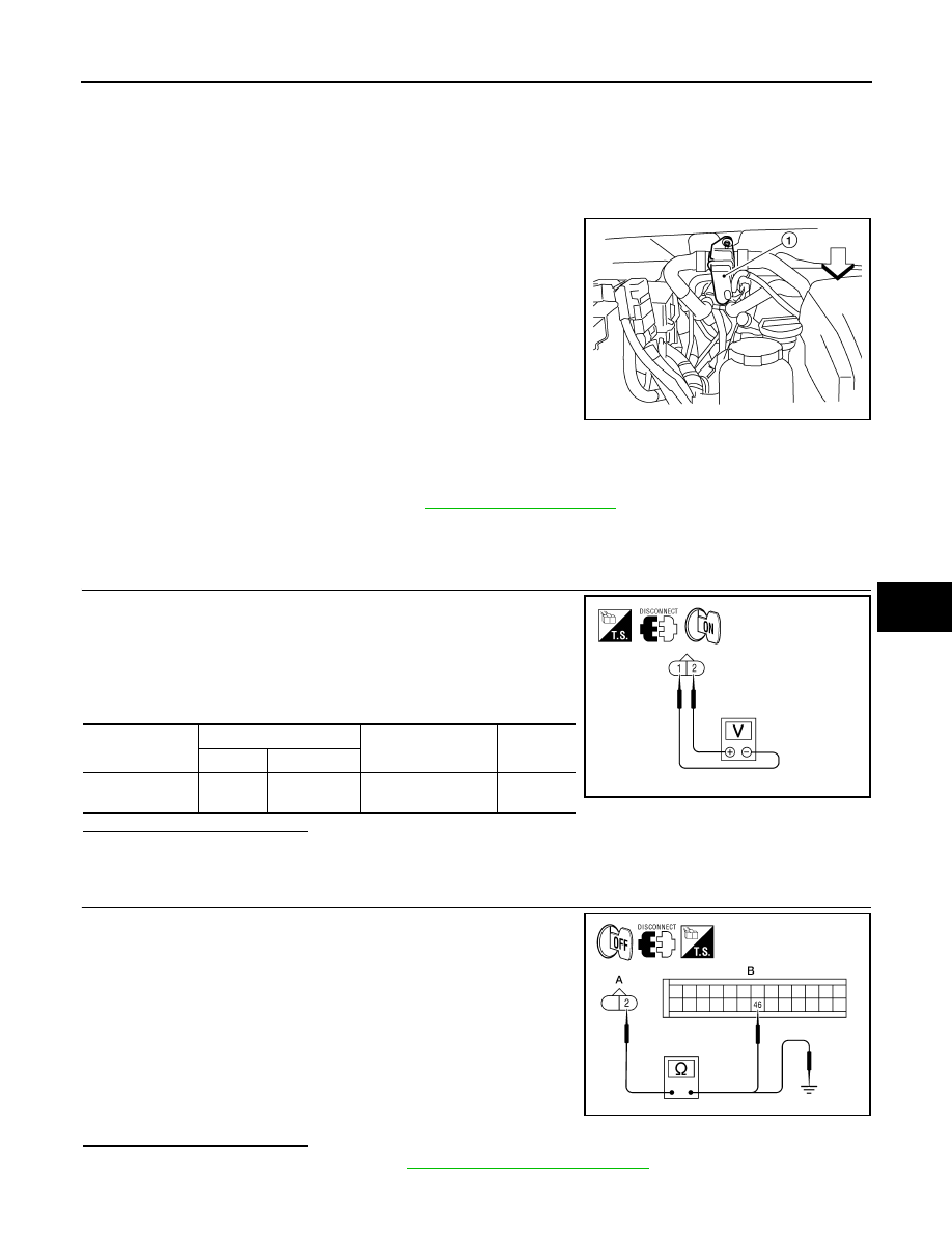
Water Valve
The water valve (1) cuts the flow of engine coolant to the front and
rear heater cores to allow for maximum cooling during A/C opera-
tion. It is controlled by the A/C auto amp.
Water Valve Diagnosis Procedure
INFOID:0000000005147717
Regarding Wiring Diagram information, refer to
DIAGNOSTIC PROCEDURE FOR WATER VALVE
1.
CHECK WATER VALVE POWER AND GROUND CIRCUITS
1. Disconnect water valve connector F68.
2. Turn ignition switch ON.
3. Rotate temperature control dial (driver) to 32
°C (90°F).
4. Check voltage between water valve harness connector F68 ter-
minal 1 and terminal 2 while rotating temperature control dial
(driver) to 18
°C (60°F).
Is the inspection result normal?
YES
>> GO TO 3.
NO
>> GO TO 2.
2.
CHECK WATER VALVE CONTROL OUTPUT CIRCUIT
1. Turn ignition switch OFF.
2. Disconnect A/C auto amp. connector M50.
3. Check continuity between water valve harness connector F68
(A) terminal 2 and A/C auto amp. harness connector M50 (B)
terminal 46.
4. Check continuity between water valve harness connector F68
terminal 2 and ground.
Is the inspection result normal?
YES
>> Replace A/C auto amp. Refer to
VTL-7, "Removal and Installation"
.
NO
>> Repair harness or connector.
WJIA1791E
Connector
Terminals
Condition
Voltage
(Approx.)
(+) (-)
Water valve: F68
2
1
Rotate temperature
control dial
Battery
voltage
WJIA1794E
2 - 46
: Continuity should exist.
2 - Ground
: Continuity should not exist.
AWIIA0203ZZ