Infiniti QX56 (JA60). Manual - part 603


  Index      Infiniti     Infiniti QX56 (JA60) - service repair manual 2010 year


Search            


Content   ..  601  602  603  604   ..


Infiniti QX56 (JA60). Manual - part 603


MAGNET CLUTCH

HAC-69

< COMPONENT DIAGNOSIS >

[AUTOMATIC AIR CONDITIONER]

C

D

E

F

G

H

J

K

L

M

A

B

HAC

N

O

P

SYMPTOM: Magnet clutch does not engage when A/C switch is ON.

1.

CHECK INTAKE AND AMBIENT SENSOR CIRCUITS

Check intake and ambient sensors. Refer to 

HAC-23, "A/C and AV Switch Assembly Self-Diagnosis"

.

Is the inspection result normal?

YES

>> GO TO 2.

NO

>> • Malfunctioning intake sensor. Refer to 

HAC-83, "Intake Sensor Diagnosis Procedure"

.

• Malfunctioning ambient sensor. Refer to 

HAC-75, "Ambient Sensor Diagnosis Procedure"

.

2.

PERFORM AUTO ACTIVE TEST

Refer to 

PCS-14, "CONSULT - III Function (IPDM E/R)"

.

Does magnet clutch operate?

YES

>> •

WITH CONSULT-III

GO TO 5.

WITHOUT CONSULT-III

GO TO 6.

NO

>> Check 10A fuse (No. 42, located in IPDM E/R), and GO TO 3.

3.

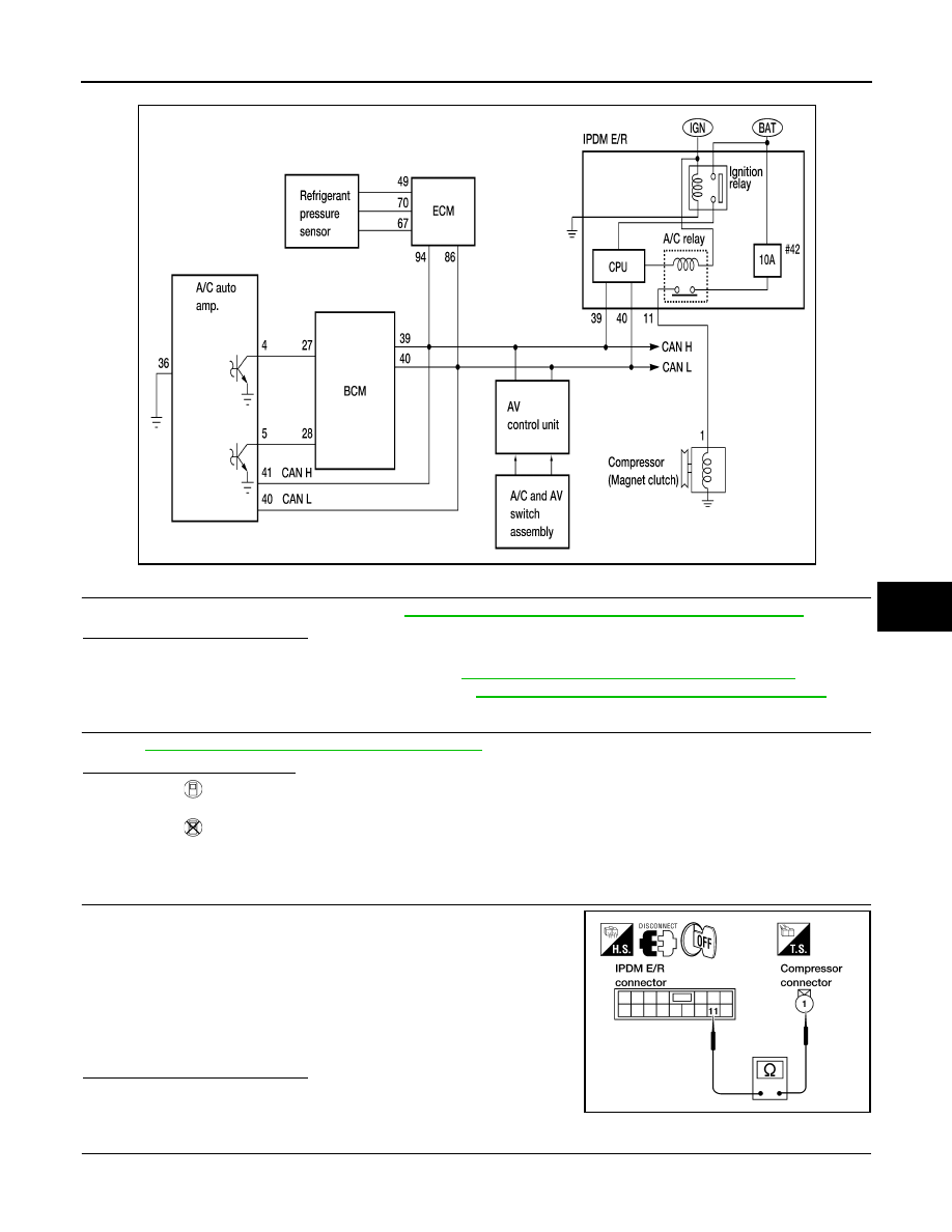
CHECK CIRCUIT CONTINUITY BETWEEN IPDM E/R AND COMPRESSOR

1. Turn ignition switch OFF.

2. Disconnect IPDM E/R connector and compressor (magnet

clutch) connector.

3. Check continuity between IPDM E/R harness connector E119

terminal 11 and A/C compressor harness connector F3 terminal

1.

Is the inspection result normal?

YES

>> GO TO 4.

NO

>> Repair harness or connector.

4.

CHECK MAGNET CLUTCH CIRCUIT

AWIIA1070GB

11 – 1

: Continuity should exist.

WJIA0560E

HAC-70

< COMPONENT DIAGNOSIS >

[AUTOMATIC AIR CONDITIONER]

MAGNET CLUTCH

Check for operation sound when applying battery voltage direct cur-

rent to terminal.
Is the inspection result normal?

YES

>> Replace IPDM E/R. Refer to 

PCS-35, "Removal and

Installation of IPDM E/R"

.

NO

>> Replace magnet clutch. Refer to 

HA-32, "Removal and

Installation for Compressor Clutch"

.

5.

CHECK BCM INPUT (COMPRESSOR ON) SIGNAL

Check compressor ON/OFF signal. Refer to 

HAC-20, "CONSULT-III Function (HVAC)"

.

Is the inspection result normal?

YES

>> GO TO 8.

NO

>> GO TO 6.

6.

CHECK CIRCUIT CONTINUITY BETWEEN BCM AND A/C AUTO AMP.

1. Turn ignition switch OFF.

2. Disconnect BCM connector and A/C auto amp. connector.

3. Check continuity between BCM harness connector M18 (A) ter-

minal 27 and A/C auto amp. harness connector M49 (B) terminal

4.

Is the inspection result normal?

YES

>> GO TO 7.

NO

>> Repair harness or connector.

7.

CHECK VOLTAGE FOR A/C AUTO AMP. (A/C COMPRESSOR ON SIGNAL)

1. Reconnect BCM connector and A/C auto amp. connector.

2. Turn ignition switch ON.

3. Check voltage between A/C auto amp. harness connector M49

terminal 4 and ground.

Is the inspection result normal?

YES

>> GO TO 8.

NO-1 >> If the voltage is approx. 5V when A/C switch is ON, replace A/C auto amp. Refer to 

VTL-7,

"Removal and Installation"

.

NO-2 >> If the voltage is approx. 0V when A/C switch is OFF, replace BCM. Refer to 

BCS-59, "Removal

and Installation"

.

8.

CHECK REFRIGERANT PRESSURE SENSOR

1. Start engine.

SJIA0197E

A/C SW ON

: COMP ON SIG ON

A/C SW OFF

: COMP ON SIG OFF

27 - 4

Continuity should exist.

AWIIA0199ZZ

Terminals

Condition

Voltage

(+)

(-)

A/C auto 

amp. con-

nector

Terminal No.

M49

4

Ground

A/C switch: ON

Approx. 0V

A/C switch: OFF

Approx. 5V

AWIIA0200ZZ

MAGNET CLUTCH

HAC-71

< COMPONENT DIAGNOSIS >

[AUTOMATIC AIR CONDITIONER]

C

D

E

F

G

H

J

K

L

M

A

B

HAC

N

O

P

2. Check voltage between ECM harness connector F54 terminal

70 and ground.

Is the inspection result normal?

YES

>> GO TO 9.

NO

>> Refer to 

EC-419, "Diagnosis Procedure"

.

9.

CHECK BCM INPUT (FAN ON) SIGNAL

Check FAN ON/OFF signal. Refer to 

HAC-20, "CONSULT-III Function (HVAC)"

.

Is the inspection result normal?

YES

>> GO TO 12.

NO

>> GO TO 10.

10.

CHECK CIRCUIT CONTINUITY BETWEEN BCM AND A/C AUTO AMP.

1. Turn ignition switch OFF.

2. Disconnect BCM connector and A/C auto amp. connector.

3. Check continuity between BCM harness connector M18 (A) ter-

minal 28 and A/C auto amp. harness connector M49 (B) terminal

5.

Is the inspection result normal?

YES

>> GO TO 11.

NO

>> Repair harness or connector.

11.

CHECK VOLTAGE FOR A/C AUTO AMP. (FAN ON SIGNAL)

1. Reconnect BCM connector and A/C auto amp. connector.

2. Turn ignition switch ON.

3. Check voltage between A/C auto amp. harness connector M49

terminal 5 and ground.

Is the inspection result normal?

YES

>> GO TO 12.

NO-1 >> If the voltage is approx. 5V when blower motor is ON, replace A/C auto amp. Refer to 

VTL-7,

"Removal and Installation"

.

Terminals

Condition

Voltage

(+)

(-)

ECM con-

nector

Terminal No.

F54

70

Ground

A/C switch: ON

Approx. 0.36 - 3.88V

LJIA0124E

FRONT BLOWER CONTROL 
DIAL ON

: FAN ON SIG ON

FRONT BLOWER CONTROL 
DIAL OFF

: FAN ON SIG OFF

28 - 5

Continuity should exist.

AWIIA0201ZZ

Terminals

Condition

Voltage

(+)

(-)

A/C auto amp. 

connector

Terminal No.

M49

5

Ground

A/C switch: ON
Blower motor 
operates

Approx. 0V

A/C switch: OFF

Approx. 5V

AWIIA0202ZZ

HAC-72

< COMPONENT DIAGNOSIS >

[AUTOMATIC AIR CONDITIONER]

MAGNET CLUTCH

NO-2 >> If the voltage is approx. 0V when blower motor is OFF, replace BCM. Refer to 

BCS-59, "Removal

and Installation"

.

12.

CHECK CAN COMMUNICATION

Check CAN communication. Refer to 

LAN-4, "System Description"

.

• BCM  –  ECM

• ECM – IPDM E/R

• ECM – A/C auto amp.
Is the inspection result normal?

YES

>> Inspection End.

NO

>> Repair or replace malfunctioning part(s).


Content   ..  601  602  603  604   ..