Infiniti QX56 (JA60). Manual - part 579
REFRIGERATION SYSTEM
HA-21
< ON-VEHICLE MAINTENANCE >
C
D
E
F
G
H
J
K
L
M
A
B
HA
N
O
P
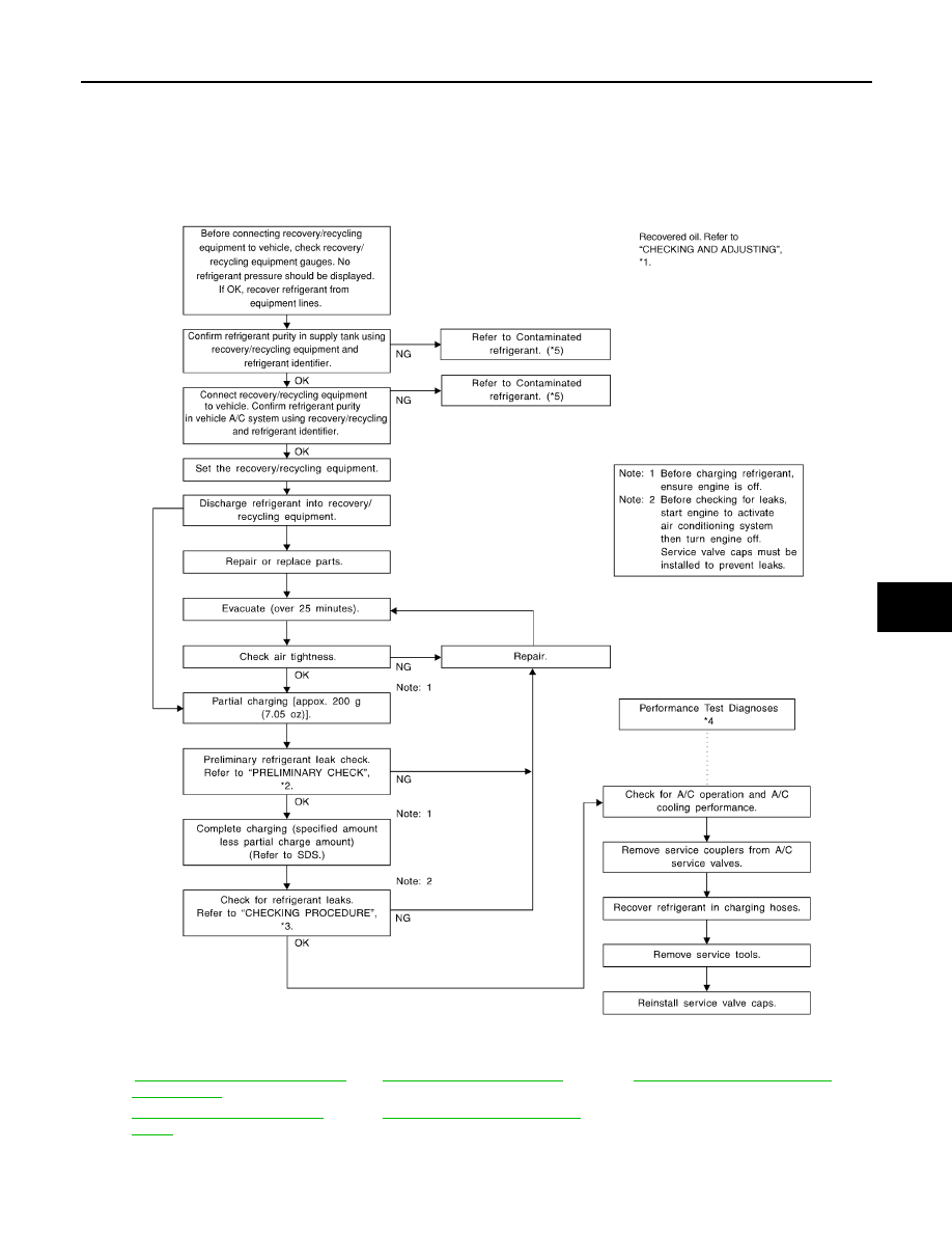
1.
Shut-off valve
2.
A/C service valve
3.
Recovery/recycling equipment
4.
Refrigerant container (HFC-134a)
5.
Weight scale (J-39650)
6.
Evacuating vacuum pump (J-39699)
7.
Manifold gauge set (J-39183)
HA-22, "Maintenance of Oil Quantity
*3
*5
HA-4, "Contaminated Refrigerant"
*2
HAC-108, "Component Function
Check"
*4
HAC-109, "Diagnostic Work Flow"
WJIA1923E