Infiniti QX56 (JA60). Manual - part 556
20
10
QUICK REFERENCE CHART: QX56
Wheelarch Height (Unladen*
1
)
INFOID:0000000001842583
Unit: mm (in)
*1: Fuel, radiator coolant and engine oil full. Spare tire, jack, hand tools and mats in designated positions.
Brake Specification
rakeINFOID:0000000001842585
Unit: mm (in)
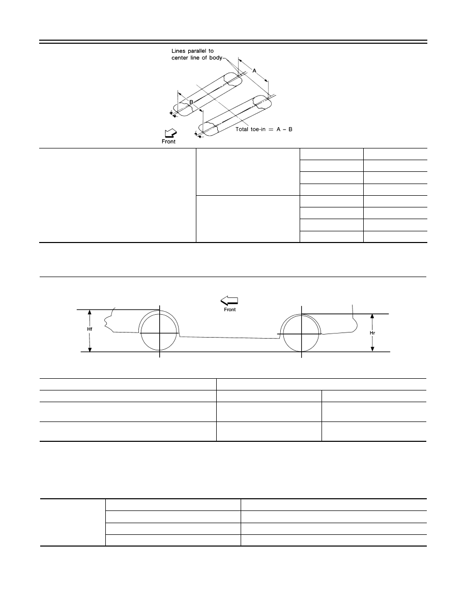
Toe-in
Distance (A - B)
Minimum
0 mm (0 in)
Nominal
3.3 mm (0.130 in)
Maximum
6.6 mm (0.260 in)
Cross toe
2 mm (0.079 in)
Angle (left, right)
Degree minute (decimal degree)
Minimum
0
° 0′ (0°)
Nominal
0
° 7′ (0.11°)
Maximum
0
° 14′ (0.22°)
Cross toe
0
° 8′ (0.14°)
SFA234AC
Suspension type
Air leveling
Applied model
2WD
4WD
Front wheelarch height (Hf)
914
(35.98)
931
(36.65)
Rear wheelarch height (Hr)
911
(35.87)
931
(36.65)
LEIA0085E
Front brake
Brake model
CLZ31VC
Rotor outer diameter
× thickness
350
× 30 (13.80 × 1.2)
Pad Length
× width × thickness
111.0
× 73.5 × 11.88 (4.73 × 2.894 × 0.374)
Cylinder bore diameter (each)
51 (2.01)