Infiniti QX56 (JA60). Manual - part 483


  Index      Infiniti     Infiniti QX56 (JA60) - service repair manual 2010 year


Search            


Content   ..  481  482  483  484   ..


Infiniti QX56 (JA60). Manual - part 483


EM-86

< DISASSEMBLY AND ASSEMBLY >

ENGINE UNIT

ASSEMBLY

1. Fully air-blow the coolant and oil passages in the cylinder block, cylinder bore, and crankcase to remove

any foreign material.

WARNING:

Use goggles to protect your eyes.

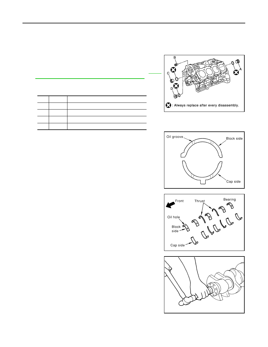
2. Install each plug to the cylinder block (only screw-type plugs are

shown).

• Apply liquid gasket. 

Use Genuine Thread Sealant or equivalent. Refer to 

GI-15,

"Recommended Chemical Products and Sealants"

.

• Replace copper washers with new ones.

• Tighten each plug as specified below.

3. Install main bearings and thrust bearings.
a. Remove any dust, dirt, and oil on the bearing mating surfaces of

the cylinder block and main bearing caps.

b. Install thrust bearings to both sides of the No. 3 journal housing

on the cylinder block and main bearing caps

• Install thrust bearings with the oil groove facing the crankshaft

arm (outside). 

• Install thrust bearings with a protrusion in the center on the

main bearing caps.

c.

Install main bearings paying attention to the direction.

• Install the one with oil holes onto the cylinder block and the

one without oil holes onto the main bearing cap.

• Before installing bearings, apply engine oil to bearing surface

(inside). Do not apply oil to the back surface, but thoroughly

clean it.

• When installing, align the bearing stopper to the notch.

• Ensure the oil holes on the cylinder block and those on the

corresponding bearing are aligned.

4. Install pilot converter to the crankshaft using suitable tool.
5. Install crankshaft to the cylinder block.

• While turning crankshaft by hand, make sure it turns smoothly. 

Part

Washer

Tightening torque

A

Yes

53.9 N·m (5.5 kg-m, 40 ft-lb)

B

No

19.6 N·m (2.0 kg-m, 15 ft-lb)

C

Yes

62.7 N·m (6.4 kg-m, 46 ft-lb)

D

Yes

62.7 N·m (6.4 kg-m, 46 ft-lb)

WBIA0419E

PBIC0093E

PBIC0094E

EMP0569D

ENGINE UNIT

EM-87

< DISASSEMBLY AND ASSEMBLY >

C

D

E

F

G

H

I

J

K

L

M

A

EM

N

P

O

6. Install main bearing caps.

• Align the identification number to the journal position to install. 

• Install it with the front mark (indicated by the arrow) facing the

front of engine. 

• Tap caps lightly to seat them in the installation position.

7. Follow the steps below to tighten each main bearing cap bolt.
a. Apply engine oil to threads and seating surfaces of bolts, and

tighten all bolts temporarily.

b. Measure tightening angle using Tool.

CAUTION:

Measure tightening angle using Tool. Do not measure visu-

ally. 

• Rotate crankshaft by hand after bolts are tightened. Check if it rotates smoothly.

• Check crankshaft side clearance. Refer to 

EM-90, "Inspection After Disassembly"

.

8. Install rear oil seal to rear oil seal retainer.

CAUTION:

Do not damage or scratch outer circumference of oil seal.

• Install new rear oil seal in the direction shown.

KBIA2533E

Main bearing cap bolts in 
order of 1 to 10

: 39.2 N·m (4.0 kg-m, 29 ft.-lb)

Main bearing cap sub 
bolts in order of 11 to 20

: 29.4 N·m (3.0 kg-m, 22 ft-lb)

PBIC0090E

Tool number

: KV10112100 (BT-8653-A)

Main bearing cap bolts in 
order of 1 to 10

: 40

°

Main bearing cap sub bolts 
in order of 11 to 20

: 30

°

Side bolts in order of 21 to 
30

: 49 N·m (5.0 kg-m, 36 ft-lb)

WBIA0597E

SEM715A

EM-88

< DISASSEMBLY AND ASSEMBLY >

ENGINE UNIT

• Tap until flattened with the front edge of the rear oil seal

retainer using suitable tool. 

• Fit the rear oil seal until it is level with the rear end surface of

rear oil seal retainer.

9. Install rear oil seal retainer.

• Apply liquid gasket thoroughly to rear oil seal retainer as

shown.

Use Genuine RTV Silicone Sealant or equivalent. Refer to

GI-15, "Recommended Chemical Products and Sealants"

.

• Apply new engine oil on the lips of rear oil seal. Do not touch.

10. Install the piston to the connecting rod. 
a. Install the snap ring to the grooves of the piston rear side.

• Insert it fully into the groove to install. 

b. Install the piston to the connecting rod.

• Heat piston until piston pin can be pushed in by hand without excess force [approx. 60

° to 70 C° (140° to

158 

°F)]. From the front to the rear, insert the piston pin into the piston and the connecting rod.

• Assemble so that the front mark on the piston crown and the

oil holes and cylinder No. on the connecting rod are positioned

as shown.

c.

Install the snap ring to the grooves of the piston front side. 

• Insert it fully into the groove to install. 

• After installing, make sure connecting rod moves smoothly.

11. Install piston rings. 

CAUTION:

Do not damage piston.

• Position each ring with the gap as shown, referring to the pis-

ton front mark.

• Install the second ring with the stamped surface facing

upward.

PBIC0097E

SBIA0391E

KBIA2534E

Stamped mark

Second ring

: 2N

PBIC0100E

ENGINE UNIT

EM-89

< DISASSEMBLY AND ASSEMBLY >

C

D

E

F

G

H

I

J

K

L

M

A

EM

N

P

O

12. Install the connecting rod bearings to the connecting rod and

connecting rod cap.

• When installing the connecting rod bearings, apply engine oil

to the bearing surface (inside). Do not apply oil to the back

surface, but thoroughly clean it.

• When installing, align the connecting rod bearing stopper pro-

trusion with the cutout of the connecting rod to install.

• Check that the oil holes on the connecting rod and those on

the corresponding bearing are aligned.

13. Install the piston and connecting rod assembly to the crankshaft

using Tool.

• Position the crankshaft pin corresponding to the connecting

rod to be installed onto bottom dead center. 

• Apply engine oil sufficiently to the cylinder bore, piston, and

crankshaft pin. 

• Match the cylinder position with the cylinder No. on the con-

necting rod to install. 

• Install the piston with the front mark on the piston crown facing

the front of the engine.

CAUTION:

Be careful not to damage the crankshaft pin, resulting from an interference of the connecting rod

big end.

14. Install connecting rod cap.

• Match the stamped cylinder number marks on the connecting

rod with those on the cylinder cap to install.   

15. Tighten connecting rod bolts using Tool.

• Apply engine oil to threads and seats of connecting rod bolts. 

• After tightening bolts, make sure the crankshaft rotates

smoothly. 

• Check connecting rod side clearance. Refer to 

EM-90,

"Inspection After Disassembly"

.

PBIC0266E

Tool number

: EM03470000 (J-8037)

WBIA0626E

KBIA2536E

Tool number

: KV10112100 (BT-8653-A)

Connecting rod bolts
Step 1

: 19.6 N·m (1.5 kg-m, 11 ft-lb)

Step 2

: 90

° clockwise

WBIA0627E


Content   ..  481  482  483  484   ..