Infiniti QX56 (JA60). Manual - part 281


  Index      Infiniti     Infiniti QX56 (JA60) - service repair manual 2010 year


Search            


Content   ..  279  280  281  282   ..


Infiniti QX56 (JA60). Manual - part 281


P1818 ACTUATOR POSITION SWITCH

DLN-47

< COMPONENT DIAGNOSIS >

[ATX14B]

C

E

F

G

H

I

J

K

L

M

A

B

DLN

N

O

P

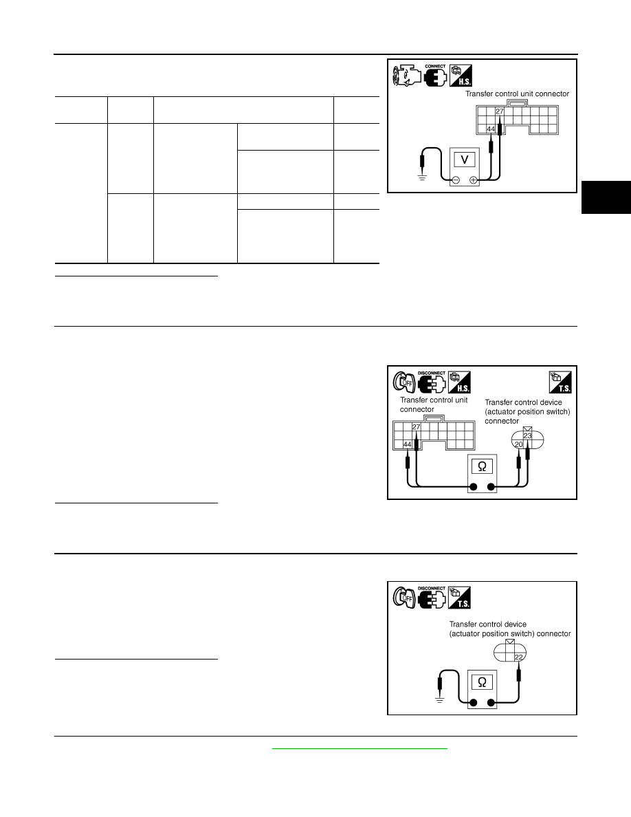
2. Check voltage between transfer control unit harness connector

terminal and ground.

Are the inspection results normal?

YES 

>> GO TO 5.

NO

>> GO TO 2.

2.

CHECK HARNESS BETWEEN TRANSFER CONTROL UNIT AND ACTUATOR POSITION SWITCH

1. Turn ignition switch OFF. (Stay for at least 5 seconds.)

2. Disconnect transfer control unit harness connector and the transfer control device (actuator position

switch) harness connector.

3. Check continuity between the following terminals.

-

Transfer control unit harness connector E143 terminal 27 and

transfer control device (actuator position switch) harness con-

nector F58 terminal 23.

-

Transfer control unit harness connector E143 terminal 44 and

transfer control device (actuator position switch) harness con-

nector F58 terminal 20.

Also check harness for short to ground and short to power.

Are the inspection results normal?

YES 

>> GO TO 3.

NO

>> Repair or replace damaged parts.

3.

CHECK GROUND CIRCUIT

1. Turn ignition switch OFF. (Stay for at least 5 seconds.)

2. Disconnect transfer control device (actuator position switch) harness connector.

3. Check continuity between transfer control device (actuator posi-

tion switch) harness connector F58 terminal 22 and ground.

Also check harness for short to ground and short to power.

Are the inspection results normal?

YES 

>> GO TO 4.

NO

>> Repair open circuit or short to ground or short to power

in harness or connectors.

4.

CHECK ACTUATOR POSITION SWITCH

1. Remove transfer control device. Refer to 

DLN-136, "Removal and Installation"

.

Connector

Terminal

Condition

Voltage 

(Approx.)

E143

27 - 

Ground

• Vehicle stopped
• Engine running
• A/T selector le-

ver N position

• Brake pedal de-

pressed

4WD shift switch: 4H, 
AUTO or 2WD

0V

4WD shift switch: 4LO

Battery 
voltage

44 - 

Ground

• Vehicle stopped
• Engine running
• A/T selector le-

ver N position

• Brake pedal de-

pressed

4WD shift switch: 4LO

0V

4WD shift switch: 
2WD, AUTO or 4H

Battery 
voltage

SDIA2715E

Continuity should exist.

SDIA2716E

Continuity should exist.

SDIA2717E

DLN-48

< COMPONENT DIAGNOSIS >

[ATX14B]

P1818 ACTUATOR POSITION SWITCH

2. Check operation by applying battery voltage to transfer control

device (actuator motor) terminals 21 and 24.

CAUTION:

• Do not operate actuator motor for more than 1 second.

• Change the actuator motor position to HIGH when install-

ing.

• Be careful not to overheat the harness.

Are the inspection results normal?

YES

>> GO TO 5.

NO

>> Replace transfer control device (actuator motor).

5.

CHECK TRANSFER CONTROL UNIT

Check transfer control unit input/output signal. Refer to 

DLN-81, "Reference Value"

.

Are the inspection results normal?

YES

>> GO TO 6.

NO

>> Check transfer control unit pin terminals for damage or loose connection with harness connector.

If any items are damaged, repair or replace damaged parts.

6.

CHECK DTC

Perform the self-diagnosis, after driving a vehicle for a while.
Are the inspection results normal?

YES

>> Inspection End.

NO

>> Replace transfer control device.

Component Inspection

INFOID:0000000005148810

1. Remove transfer control device. Refer to 

DLN-136, "Removal and Installation"

.

2. Check operation by applying battery voltage to transfer control

device (actuator motor) terminals 21 and 24.

CAUTION:

• Do not operate actuator motor for more than 1 second.

• Change the actuator motor position to HIGH when install-

ing.

• Be careful not to overheat the harness.

3. If the inspection results are abnormal replace transfer control device (actuator motor).

Terminal

Continuity

Continuity

24 (Battery voltage) - 21 

(Ground)

20 - 22

Yes

22 - 23

No

21 (Battery voltage) - 24 

(Ground)

22 - 23

Yes

20 - 22

No

LDIA0101E

Terminal

Continuity

Continuity

24 (Battery voltage) - 21 

(Ground)

20 - 22

Yes

22 - 23

No

21 (Battery voltage) - 24 

(Ground)

22 - 23

Yes

20 - 22

No

LDIA0101E

P1819 TRANSFER CONTROL DEVICE

DLN-49

< COMPONENT DIAGNOSIS >

[ATX14B]

C

E

F

G

H

I

J

K

L

M

A

B

DLN

N

O

P

P1819 TRANSFER CONTROL DEVICE

Description

INFOID:0000000005148811

The transfer control device integrates the actuator motor and actuator position switch.  DTC P1819 will set if

either of the following conditions exist:

• Malfunction occurs in transfer control device actuator circuit.

• Malfunction is detected in the transfer shut off relay.

DTC Logic

INFOID:0000000005148812

DTC DETECTION LOGIC

DTC CONFIRMATION PROCEDURE

1.

DTC CONFIRMATION PROCEDURE

1. Turn ignition switch ON.

2. Perform self-diagnosis.
Is DTC P1819 detected?

YES

>> Perform diagnosis procedure. Refer to 

DLN-49, "Diagnosis Procedure"

.

NO

>> Inspection End.

Diagnosis Procedure

INFOID:0000000005148813

Regarding Wiring Diagram information, refer to 

DLN-89, "Wiring Diagram - ALL-MODE 4WD SYSTEM -"

.

1.

CHECK POWER SUPPLY

1. Turn ignition switch OFF. (Stay for at least 5 seconds.)

2. Connect transfer control unit harness connector.

3. Check voltage between transfer control unit harness connector

terminal and ground.

DTC

CONSULT-III

Diagnostic item is detected when...

Reference

[P1819]

SHIFT ACT CIR

• Transfer control device actuator circuit 

is shorted or open. (Malfunctions are 
detected when transfer shift relay cir-
cuit is open/shorted or relay monitor 
circuit is open/shorted.)

• Malfunction occurs in transfer control 

device drive circuit.

• Malfunction is detected in transfer 

shut off relay.

Refer to 

DLN-49

.

Connector

Terminal

Voltage (Approx.)

E142

16 - Ground

0V

22 - Ground

E143

30 - Ground

Battery voltage

SDIA2834E

DLN-50

< COMPONENT DIAGNOSIS >

[ATX14B]

P1819 TRANSFER CONTROL DEVICE

4. Turn ignition switch ON. (Do not start engine.)

5. Check voltage between transfer control unit harness connector

terminals and ground.

Are the inspection results normal?

YES

>> GO TO 2.

NO

>> Check the following. If any items are damaged, repair or replace damaged parts.

• 10A fuse (No. 26 located in the fuse and fusible link box).

• Harness for short or open between battery and transfer shut off relay harness connector E69

terminal 1.

• Harness for short or open between transfer shut off relay harness connector E69 terminal 2  and

transfer control unit harness connector E143 terminal 30.

• Harness for short or open between battery and transfer shut off relay harness connector E69

terminal 5.

• Harness for short or open between transfer shut off relay harness connector E69 terminal 3 and

transfer control unit harness connector E142 terminal 22.

• Transfer shut off relay. Refer to 

DLN-23, "Component Inspection"

.

2.

CHECK GROUND CIRCUIT

1. Turn ignition switch OFF. (Stay for at least 5 seconds.)

2. Disconnect transfer control unit harness connector.

3. Check continuity between transfer control unit harness connec-

tor E142 terminals 3, 6, E143 terminal 45 and ground.

Also check harness for short to ground and short to power.

Are the inspection results normal?

YES

>> GO TO 3.

NO

>> Repair open circuit or short to ground or short to power

in harness or connectors.

3.

CHECK ACTUATOR MOTOR POWER SUPPLY CIRCUIT

1. Turn ignition switch OFF. (Stay for at least 5 seconds.)

2. Remove transfer shift high relay and transfer shift low relay. Refer to 

DLN-16, "Component Parts Loca-

tion"

.

3. Check voltage between transfer shift high relay harness connec-

tor E46 terminal 5 (A), transfer shift low relay harness connector

E47 terminal 5 (B) and ground.

Connector

Terminal

Voltage (Approx.)

E142

16 - Ground

Battery voltage

22 - Ground

E143

30 - Ground

0V

SDIA2835E

Continuity should exist.

SDIA2691E

Connector

Terminal

Voltage (Approx.)

A: E46

5 - Ground

Battery voltage

B: E47

5 - Ground

WDIA0310E


Content   ..  279  280  281  282   ..