Infiniti QX56 (JA60). Manual - part 280


  Index      Infiniti     Infiniti QX56 (JA60) - service repair manual 2010 year


Search            


Content   ..  278  279  280  281   ..


Infiniti QX56 (JA60). Manual - part 280


P1817 ACTUATOR MOTOR

DLN-43

< COMPONENT DIAGNOSIS >

[ATX14B]

C

E

F

G

H

I

J

K

L

M

A

B

DLN

N

O

P

Are the inspection results normal?

YES

>> GO TO 5.

NO

>> Replace the transfer shut off relay.  Refer to 

DLN-16, "Component Parts Location"

.

5.

CHECK HARNESS BETWEEN TRANSFER CONTROL UNIT AND TRANSFER SHIFT RELAY

1. Turn ignition switch OFF. (Stay for at least 5 seconds.)

2. Disconnect transfer control unit harness connector and the transfer control device (actuator motor) har-

ness connector.

3. Remove transfer shift high relay and transfer shift low relay.

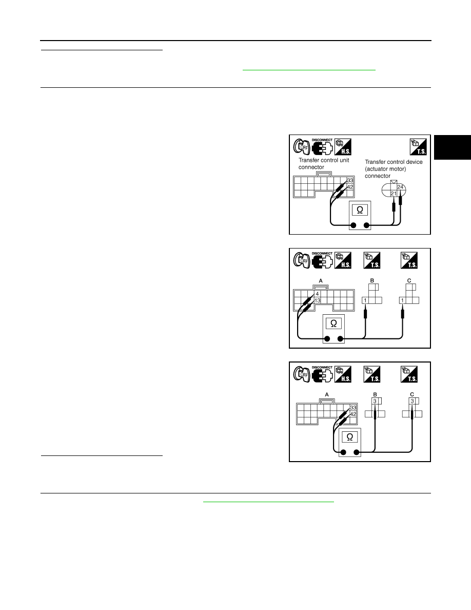
4. Check continuity between the following terminals.

-

Transfer control unit harness connector E143 terminal 33 and

transfer control device (actuator motor) harness connector F58

terminal 21.

-

Transfer control unit harness connector E143 terminal 42 and

transfer control device (actuator motor) harness connector F58

terminal 24.

-

Transfer control unit harness connector E142 (A) terminal 4 and

transfer shift high relay harness connector E46 (B) terminal 1.

-

Transfer control unit harness connector E142 (A) terminal 13

and transfer shift low relay harness connector E47 (C) terminal

1.

-

Transfer control unit harness connector E143 (A) terminal 33

and transfer shift high relay harness connector E46 (B) terminal

3.

-

Transfer control unit harness connector E143 (A) terminal 42

and transfer shift low relay harness connector E47 (C) terminal

3.

Also check harness for short to ground and short to power.

Are the inspection results normal?

YES

>> GO TO 6.

NO

>> Repair or replace damaged parts.

6.

CHECK ACTUATOR MOTOR

1. Remove transfer control device. Refer to 

DLN-136, "Removal and Installation"

.

SDIA2710E

WDIA0314E

Continuity should exist.

WDIA0315E

DLN-44

< COMPONENT DIAGNOSIS >

[ATX14B]

P1817 ACTUATOR MOTOR

2. Check operation by applying battery voltage to transfer control

device (actuator motor) terminals 21 and 24.

CAUTION:

• Do not operate actuator motor for more than 1 second.

• Change the actuator motor position to HIGH when install-

ing.

• Be careful not to overheat the harness.

3. Check resistance between transfer control device (actuator

motor) terminals 21 and 24.

Are the inspection results normal?

YES

>> GO TO 7.

NO

>> Replace transfer control device (actuator motor).

7.

CHECK TRANSFER CONTROL UNIT

Check transfer control unit input/output signal. Refer to 

DLN-81, "Reference Value"

.

Are the inspection results normal?

YES

>> GO TO 8.

NO

>> Check transfer control unit pin terminals for damage or loose connection with harness connector.

If any items are damaged, repair or replace damaged parts.

8.

CHECK DTC

Perform the self-diagnosis, after driving a vehicle for a while.
Are the inspection results normal?

YES

>> Inspection End.

NO

>> Replace transfer control unit. Refer to 

DLN-130, "Removal and Installation"

.

Component Inspection

INFOID:0000000005148806

TRANSFER SHIFT RELAY

1. Turn ignition switch OFF. (Stay for at least 5 seconds.)
2. Remove transfer shift high relay and transfer shift low relay. Refer to 

DLN-16, "Component Parts Loca-

tion"

.

3. Apply 12V direct current between transfer shift relay terminals 1

and 2.

4. Check continuity between relay terminals 3 and 4, 3 and 5.

5. If NG, replace transfer shift relay.

TRANSFER CONTROL DEVICE

1. Remove transfer control device. Refer to 

DLN-136, "Removal and Installation"

.

Terminal

Actuator motor

21 (Battery voltage) - 24 (Ground)

Clockwise rotation

24 (Battery voltage) - 21 (Ground)

Counterclockwise rotation

21 - 24 : Approx. 0.2 

WDIA0224E

SDIA2726E

Terminal

Condition

Continuity

3 - 4

12V direct current supply between terminals 1 and 2

No

OFF

Yes

3 - 5

12V direct current supply between terminals 1 and 2

Yes

OFF

No

WIIA0291E

P1817 ACTUATOR MOTOR

DLN-45

< COMPONENT DIAGNOSIS >

[ATX14B]

C

E

F

G

H

I

J

K

L

M

A

B

DLN

N

O

P

2. Check operation by applying battery voltage to transfer control

device (actuator motor) terminals 21 and 24.

CAUTION:

• Do not operate actuator motor for more than 1 second.

• Change the actuator motor position to HIGH when install-

ing.

• Be careful not to overheat the harness.

3. Check resistance between transfer control device (actuator

motor) terminals 21 and 24.

4. If NG, replace transfer control device (actuator motor).

Terminal

Actuator motor

21 (Battery voltage) - 24 (Ground)

Clockwise rotate

24 (Battery voltage) - 21 (Ground)

Counterclockwise rotate

WDIA0224E

21 - 24 : Approx. 0.2 

SDIA2726E

DLN-46

< COMPONENT DIAGNOSIS >

[ATX14B]

P1818 ACTUATOR POSITION SWITCH

P1818 ACTUATOR POSITION SWITCH

Description

INFOID:0000000005148807

The actuator position switch detects the current actuator motor range.  DTC P1818 will set if either of the fol-

lowing occur:

• Improper signal from actuator position switch is input due to open or short circuit.

• Malfunction is detected in actuator position switch.

DTC Logic

INFOID:0000000005148808

DTC DETECTION LOGIC

DTC CONFIRMATION PROCEDURE

1.

DTC CONFIRMATION PROCEDURE

1. Turn ignition switch ON.

2. Perform self-diagnosis.
Is DTC P1818 detected?

YES

>> Perform diagnosis procedure. Refer to 

DLN-46, "Diagnosis Procedure"

.

NO

>> Inspection End.

Diagnosis Procedure

INFOID:0000000005148809

Regarding Wiring Diagram information, refer to 

DLN-89, "Wiring Diagram - ALL-MODE 4WD SYSTEM -"

.

1.

CHECK ACTUATOR POSITION SWITCH SIGNAL

With CONSULT-III

1. Start engine.

2. Select DATA MONITOR mode for ALL MODE AWD/4WD with CONSULT-III.

3. Read out the value of SHIFT POS SW1 and SHIFT POS SW2.

Without CONSULT-III

1. Start engine.

DTC

CONSULT-III

Diagnostic item is detected when...

Reference

[P1818]

SHIFT ACT POSI SW

• Improper signal from actuator position 

switch is input due to open or short cir-
cuit.

• Malfunction is detected in the actuator 

position switch.

Refer to 

DLN-46

.

Monitored item

Condition

Display value

SHIFT POS SW1

• Vehicle stopped
• Engine running
• A/T selector lever 

N position

• Brake pedal de-

pressed

4WD shift switch: 4LO

ON

4WD shift switch: 
2WD, AUTO or 4H

OFF

SHIFT POS SW2

• Vehicle stopped
• Engine running
• A/T selector lever 

N position

• Brake pedal de-

pressed

4WD shift switch: 4H, 
AUTO or 2WD

ON

4WD shift switch: 4LO

OFF


Content   ..  278  279  280  281   ..