Infiniti QX56 (JA60). Manual - part 240
BACK DOOR CLOSE (CLOSE) SWITCH SYSTEM
DLK-131
< COMPONENT DIAGNOSIS >
[WITH INTELLIGENT KEY SYSTEM]
C
D
E
F
G
H
I
J
L
M
A
B
DLK
N
O
P
BACK DOOR CLOSE (CLOSE) SWITCH SYSTEM
Diagnosis Procedure
INFOID:0000000005147001
Regarding Wiring Diagram information, refer to
DLK-199, "Wiring Diagram—AUTOMATIC BACK DOOR SYS-
1.
BACK DOOR CLOSE SWITCH FUNCTION INSPECTION
Check back door close (close) switch using switch operation.
Is the inspection result normal?
YES
>> Back door close switch is OK.
NO
>> GO TO 2
2.
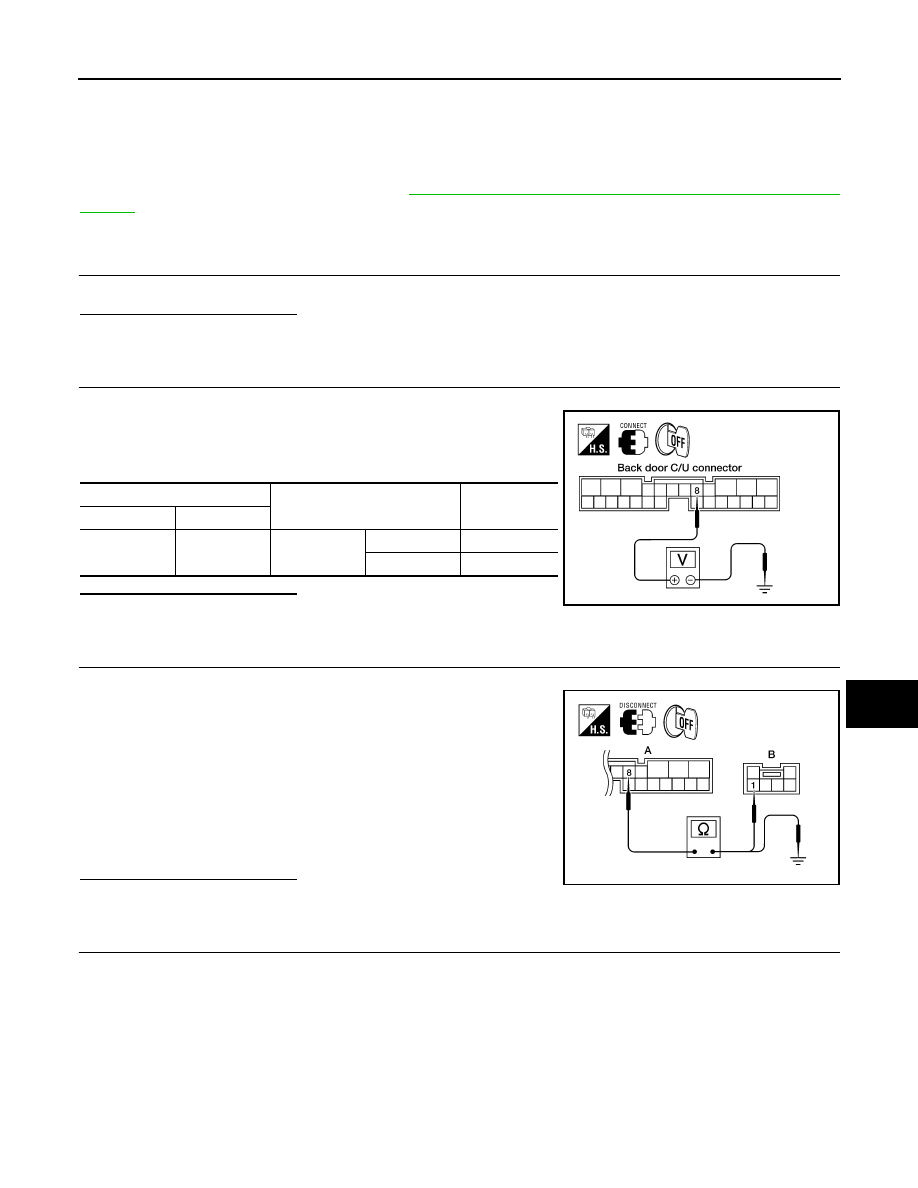
BACK DOOR CLOSE SWITCH SIGNAL INSPECTION
1. Turn ignition switch OFF.
2. While operating the back door close switch, check voltage
between back door control unit connector B55 terminal 8 and
ground.
Is the inspection result normal?
YES
>> Switch is OK.
NO
>> GO TO 3
3.
BACK DOOR CLOSE SWITCH CIRCUIT INSPECTION
1. Disconnect back door close switch and back door control unit connector.
2. Check continuity between back door control unit connector (A)
B55 terminal 8 and back door close switch connector (B) B63
terminal 1.
3. Check continuity between back door control unit connector (A)
B55 terminal 8 and ground.
Is the inspection result normal?
YES
>> GO TO 4
NO
>> Repair the harness between the back door close switch and the back door control unit.
4.
BACK DOOR CLOSE SWITCH GROUND INSPECTION
Terminals
Measuring condition
Voltage (V)
(Approx.)
(+)
(-)
8
Ground
Back door
close switch
ON
0
OFF
Battery voltage
LIIA0805E
8 - 1
: Continuity should exist.
8 - Ground : Continuity should not exist.
ALKIA0669ZZ