Infiniti QX56 (JA60). Manual - part 228


  Index      Infiniti     Infiniti QX56 (JA60) - service repair manual 2010 year


Search            


Content   ..  226  227  228  229   ..


Infiniti QX56 (JA60). Manual - part 228


DOOR REQUEST SWITCH

DLK-83

< COMPONENT DIAGNOSIS >

[WITH INTELLIGENT KEY SYSTEM]

C

D

E

F

G

H

I

J

L

M

A

B

DLK

N

O

P

DOOR REQUEST SWITCH

Description

INFOID:0000000005146942

Transmits lock/unlock operation to Intelligent Key unit.

Component Function Check

INFOID:0000000005146943

1.

CHECK FUNCTION

 With CONSULT-III

Check door request switch "DR REQ SW" and "AS REQ SW" in DATA MONITOR mode.

Is the inspection result normal?

YES

>> Door request switch is OK.

NO

>> Refer to 

DLK-83, "Diagnosis Procedure"

.

Diagnosis Procedure

INFOID:0000000005146944

Regarding Wiring Diagram information, refer to 

DLK-178, "Wiring Diagram — INTELLIGENT KEY SYSTEM —

"

.

1.

CHECK FRONT DOOR REQUEST SWITCH

With CONSULT-III

Check front door request switch (“DR REQ SW” or “AS REQ SW”) in “DATA MONITOR” mode.
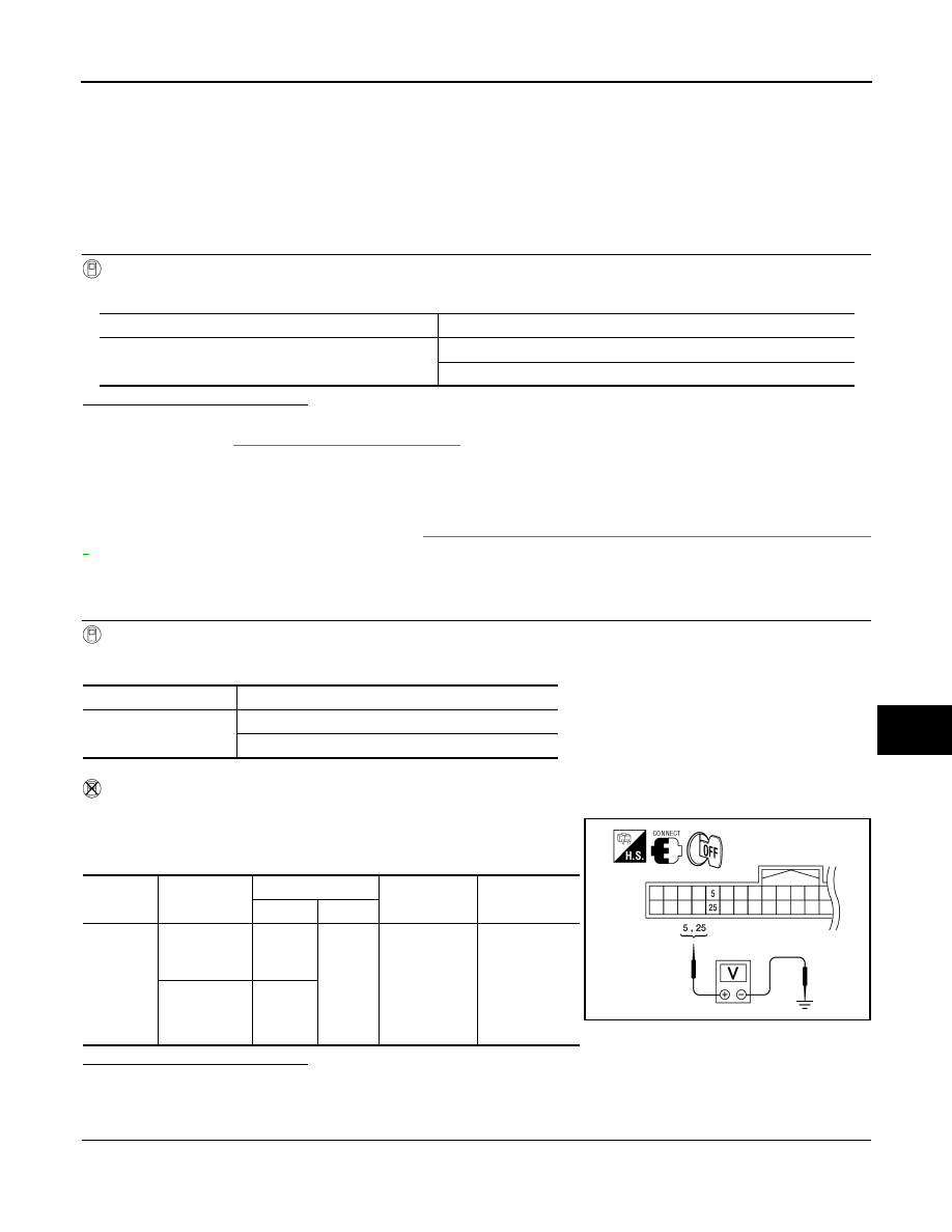
Without CONSULT-III

1. Turn ignition switch OFF.

2. Check voltage between Intelligent Key unit harness connector

M70 terminals 5, 25 and ground.

Is the inspection result normal?

YES

>> Front door request switch is OK.

NO

>> GO TO 2

2.

CHECK FRONT DOOR REQUEST SWITCH CIRCUIT

1. Turn ignition switch OFF.

2. Disconnect Intelligent Key unit and front door request switch connectors.

Monitor item

Condition

DR REQ SW
AS REQ SW

Door request switch is pressed : ON

Door request switch is released : OFF

Monitor item

Condition

DR REQ SW
AS REQ SW

Front door request switch is pressed: ON

Front door request switch is released: OFF

Connector

Item

Terminals

Condition

Voltage (V)

(Approx.)

(+)

(–)

M70

Front door re-
quest switch 
LH

5

Ground

Door request 

switch is 

pressed

Door request 

switch is re-

leased

0

Battery voltage

Front door re-
quest switch 
RH

25

WIIA1183E

DLK-84

< COMPONENT DIAGNOSIS >

[WITH INTELLIGENT KEY SYSTEM]

DOOR REQUEST SWITCH

3. Check continuity between Intelligent Key unit harness connector (A) M70 terminals 5 (driver door), 25

(passenger door) and front door request switch harness connector (B) D16 (LH), D116 (RH) terminal 1.

4. Check continuity between Intelligent Key unit harness connector

(A) M70 terminals 5 (driver door), 25 (passenger door) and

ground.

Is the inspection result normal?

YES

>> GO TO 3

NO

>> Repair or replace harness between Intelligent Key unit and front door request switch.

3.

CHECK FRONT DOOR REQUEST SWITCH GROUND CIRCUIT

Check continuity between front door request switch harness connector D16 (driver door), D116 (passenger

door) terminal 2 and ground.

Is the inspection result normal?

YES

>> GO TO 4

NO

>> Repair or replace door request switch ground circuit.

4.

CHECK FRONT DOOR REQUEST SWITCH OPERATION

Refer to 

DLK-85, "Component Inspection"

.

Is the inspection result normal?

YES

>> GO TO 5

NO

>> Replace front door request switch.

5.

CHECK FRONT DOOR REQUEST SWITCH SIGNAL

1. Connect Intelligent Key unit connector.

2. Check voltage between Intelligent Key unit harness connector

M70 terminals 5, 25 and ground.

Is the inspection result normal?

YES

>> Refer to 

GI-38, "Intermittent Incident"

.

NO

>> Replace Intelligent Key unit. Refer to 

SEC-120, "Removal and Installation"

.

Driver side

5 - 1

: Continuity should exist.

Passenger side

25 - 1

: Continuity should exist.

5 - Ground

: Continuity should not exist.

25 - Ground

: Continuity should not exist.

PIIB6614E

2 - Ground

: Continuity should exist.

PIIB6616E

Connector

Item

Terminals

Condition

Voltage (V)

(Approx.)

(+)

(–)

M70

Front door re-
quest switch 
LH

5

Ground

Door request 

switch is 

pressed

Door request 

switch is re-

leased

0

Battery voltage

Front door re-
quest switch 
RH

25

WIIA1183E

DOOR REQUEST SWITCH

DLK-85

< COMPONENT DIAGNOSIS >

[WITH INTELLIGENT KEY SYSTEM]

C

D

E

F

G

H

I

J

L

M

A

B

DLK

N

O

P

Component Inspection

INFOID:0000000005146945

1.

CHECK FRONT DOOR REQUEST SWITCH OPERATION

1. Turn ignition switch OFF.

2. Disconnect front door request switch connector.

3. Check continuity between front door request switch terminals 1

and 2.

Is the inspection result normal?

YES

>> Inspection End.

NO

>> Replace front door request switch.

Component

Terminals

Condition

Continuity

Front door request 
switch (LH or RH)

1

2

Front door request 
switch is pressed

Yes

Front door request 
switch is released

No

PIIB6615E

DLK-86

< COMPONENT DIAGNOSIS >

[WITH INTELLIGENT KEY SYSTEM]

DOOR LOCK ACTUATOR

DOOR LOCK ACTUATOR

DRIVER SIDE
DRIVER SIDE : Description

INFOID:0000000005146946

Locks/unlocks the door with the signal from BCM.

DRIVER SIDE : Component Function Check

INFOID:0000000005146947

1.

CHECK FUNCTION

1. Use CONSULT-III to perform Active Test "DOOR LOCK".

2. Touch “ALL LOCK” or “ALL UNLOCK” to check that it works normally.
Is the inspection result normal?

YES

>> Door lock actuator is OK.

NO

>> Refer to 

DLK-86, "DRIVER SIDE : Diagnosis Procedure"

.

DRIVER SIDE : Diagnosis Procedure

INFOID:0000000005146948

Regarding Wiring Diagram information, refer to 

DLK-157, "Wiring Diagram — POWER DOOR LOCK SYS-

TEM —"

.

1.

CHECK DOOR LOCK ACTUATOR SIGNAL

1. Turn ignition switch OFF.

2. Check voltage between BCM connector M20 terminals 59, 65

and ground.

Is the inspection result normal?

YES

>> GO TO 2

NO

>> GO TO 3

2.

CHECK DOOR LOCK ACTUATOR HARNESS

1. Disconnect BCM and front door lock assembly LH (actuator).

2. Check continuity between BCM connector (A) M20 terminals 59,

65 and front door lock assembly LH (actuator) connector (B)

D14 terminals 2, 3. 

Is the inspection result normal?

YES

>> Replace front door lock assembly LH (actuator).

Connector

Terminals

Condition

Voltage (V)

(Approx.)

(+)

(-)

M20

59

Ground

Driver door lock/unlock 
switch is turned to UN-
LOCK

→ Battery voltage

65

Driver door lock/unlock 
switch is turned to LOCK

→ Battery voltage

LIIA1046E

Connector

Terminals

Connector

Terminals

Continuity

M20

59

D14

2

Yes

65

3

Yes

ALKIA0632ZZ


Content   ..  226  227  228  229   ..