Infiniti QX56 (JA60). Manual - part 142
VDC OFF SWITCH
BRC-81
< COMPONENT DIAGNOSIS >
[VDC/TCS/ABS]
C
D
E
G
H
I
J
K
L
M
A
B
BRC
N
O
P
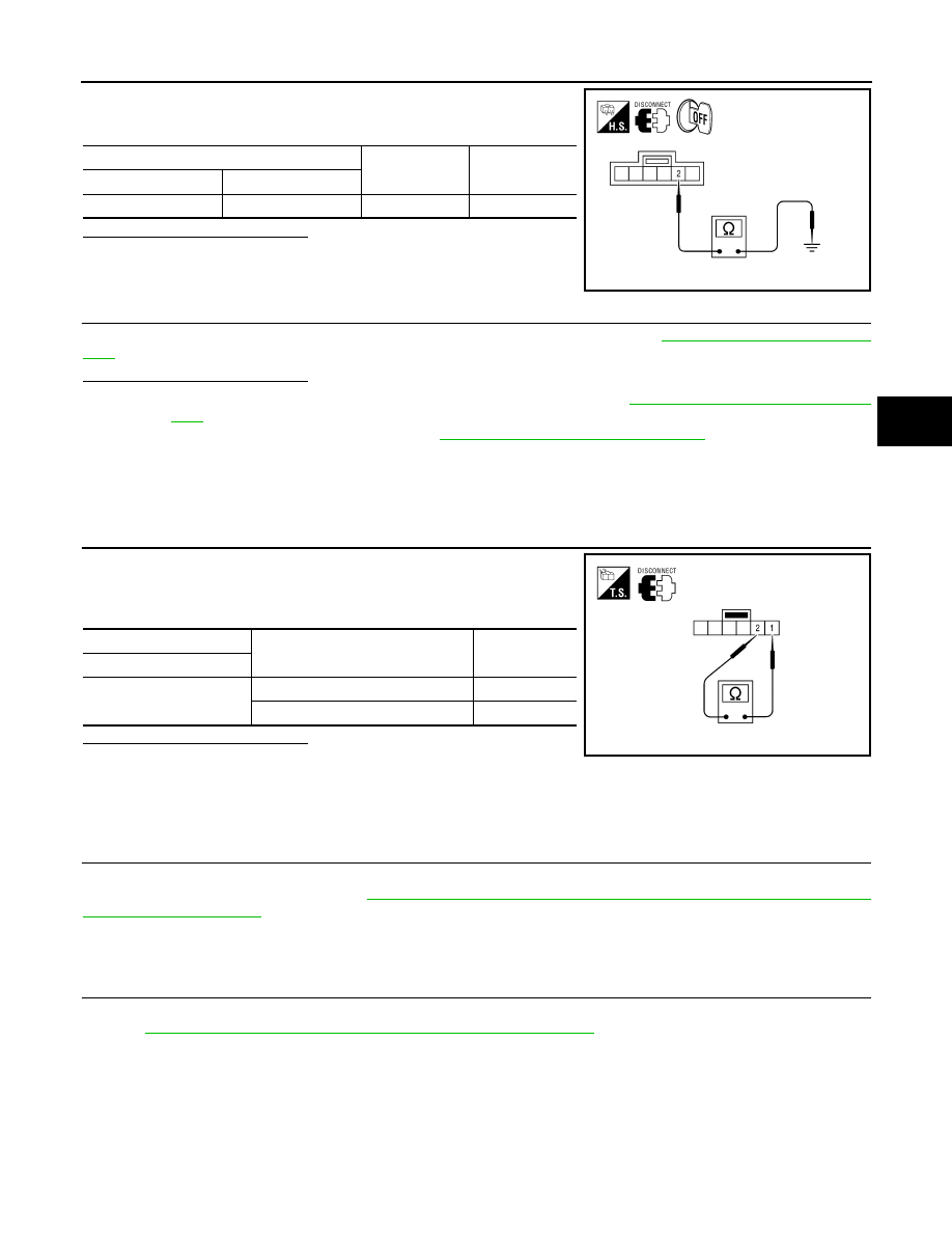
Check continuity between VDC OFF switch connector M253 terminal
2 and ground.
Is the inspection result normal?
YES
>> GO TO 4
NO
>> Repair or replace harness.
4.
CHECK COMBINATION METER
Check if the indication and operation of combination meter are normal. Refer to
.
Is the inspection result normal?
YES
>> Replace ABS actuator and electric unit (control unit). Refer to
BRC-116, "Removal and Installa-
.
NO
>> Replace combination meter. Refer to
MWI-100, "Removal and Installation"
Component Inspection
INFOID:0000000005148068
INSPECTION PROCEDURE
1.
CHECK VDC OFF SWITCH
1. Turn ignition switch OFF.
2. Disconnect VDC OFF switch connector.
3. Check continuity between VDC OFF switch terminals.
Is the inspection result normal?
YES
>> Inspection End
NO
>> Replace VDC OFF switch.
Special Repair Requirement
INFOID:0000000005194924
1.
ADJUSTMENT OF STEERING ANGLE SENSOR NEUTRAL POSITION
Always perform neutral position adjustment for the steering angle sensor when replacing the ABS actuator
and electric unit (control unit). Refer to
BRC-8, "ADJUSTMENT OF STEERING ANGLE SENSOR NEUTRAL
.
>> GO TO 2
2.
CALIBRATION OF DECEL G SENSOR
Always perform calibration of decel G sensor when replacing the ABS actuator and electric unit (control unit).
BRC-9, "CALIBRATION OF DECEL G SENSOR : Description"
>> END
VDC OFF switch
—
Continuity
Connector
Terminal
M253
2
Ground
Yes
AWFIA0031ZZ
VDC OFF switch
Condition
Continuity
Terminal
1
− 2
When VDC OFF switch is pressed.
Yes
When VDC OFF switch is released.
No
AWFIA0446ZZ