Content .. 998 999 1000 1001 ..
Infiniti QX56 (JA60). Manual - part 1000
DUCTS AND GRILLES
VTL-35
< ON-VEHICLE REPAIR >
C
D
E
F
G
H
J
K
L
M
A
B
VTL
N
O
P
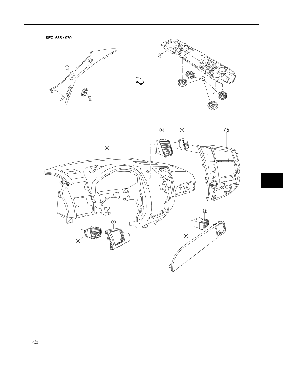
Grilles
ALIIA0067ZZ
1.
Front pillar finisher (RH shown LH
similar)
2.
Side demister grille (RH shown LH
similar)
3.
Rear roof console
4.
Rear roof console grilles
5.
Instrument panel
6.
Side ventilator grille (LH)
7.
Instrument side finisher (LH)
8.
Ventilator grille (LH)
9.
Ventilator grille (RH)
10. Cluster lid C
11. Instrument side finisher (RH)
12. Side ventilator grille (RH)
Front