Infiniti QX56 (JA60). Manual - part 90
 

  Index      Infiniti     Infiniti QX56 (JA60) - service repair manual 2010 year


Search            


Content   ..  88  89  90  91   ..


Infiniti QX56 (JA60). Manual - part 90


AV-168

< PREPARATION >

[AUDIO SYSTEM]

PREPARATION

PREPARATION

PREPARATION

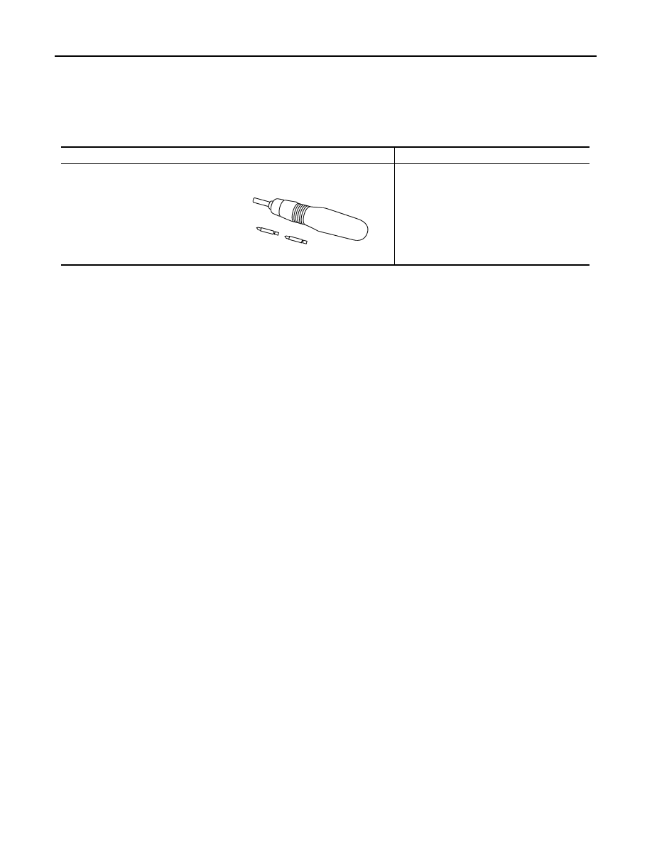
Commercial Service Tools

INFOID:0000000005146355

Tool name

Description

Power tool

Loosening bolts and nuts

PBIC0191E

AV

AV CONTROL UNIT

AV-169

< ON-VEHICLE REPAIR >

[AUDIO SYSTEM]

C

D

E

F

G

H

I

J

K

L

M

B

A

O

P

ON-VEHICLE REPAIR

AV CONTROL UNIT

Removal and Installation

INFOID:0000000005146356

CAUTION:

1.

Cluster lid C

2.

AV switch 

3.

AV control unit

4.

AV control unit brackets

5.

Tuner knob switch

6.

A/C and AV switch assembly

7.

Volume knob switch

8.

Volume knob

9.

Temp knobs RH and LH

10. Enter button

11. Tuner knob

ALNIA0201ZZ

AV-170

< ON-VEHICLE REPAIR >

[AUDIO SYSTEM]

AV CONTROL UNIT

Only remove and replace the A/C or AV switch assembly knobs if damaged or missing. The knobs

must not be removed from the switches when removing and installing the A/C or AV switch assembly

to prevent damage to the switch assembly.

REMOVAL

1. Disconnect the battery negative terminal.
2. Remove the cluster lid C. Refer to 

IP-15, "Removal and Installation"

.

3. Remove the AV control unit screws, using a power tool.
4. Remove the AV control unit.
5. Remove the A/C and AV switch assembly screws, then remove the A/C and AV switch assembles as nec-

essary.

INSTALLATION

Installation is in the reverse order of removal.

AV

DISPLAY UNIT

AV-171

< ON-VEHICLE REPAIR >

[AUDIO SYSTEM]

C

D

E

F

G

H

I

J

K

L

M

B

A

O

P

DISPLAY UNIT

Removal and Installation

INFOID:0000000005146357

REMOVAL

1. Remove cluster lid C. Refer to 

IP-15, "Removal and Installation"

.

2. Remove the display unit screws (A), pull out the display unit (1)

from instrument panel, to disconnect the display unit connectors.

3. Remove the A/C auto amp. screws (A) and the A/C auto amp.

(1).

• Display unit (2)

4. Remove the display unit bracket screws and the display unit

brackets.

INSTALLATION

Installation is in the reverse order of removal.

ALNIA0272ZZ

ALIIA0063ZZ


Content   ..  88  89  90  91   ..