Infiniti QX56 (JA60). Manual - part 25


  Index      Infiniti     Infiniti QX56 (JA60) - service repair manual 2010 year


Search            


Content   ..  23  24  25  26   ..


Infiniti QX56 (JA60). Manual - part 25


PEDAL ADJUSTING SENSOR

ADP-91

< COMPONENT DIAGNOSIS >

C

D

E

F

G

H

I

K

L

M

A

B

ADP

N

O

P

PEDAL ADJUSTING SENSOR

Description

INFOID:0000000005147541

• The pedal adjusting sensor is installed to the pedal assembly. 

• The resistance of pedal adjusting sensor is changed according to the forward/backward position of pedal

assembly.

• The terminal voltage of automatic drive positioner control unit will be changed according to a change of

pedal adjusting sensor resistance. Automatic drive positioner control unit calculates the pedal assembly

position from the voltage.

Component Function Check

INFOID:0000000005147542

1.

 CHECK FUNCTION

1. Select “PEDAL SEN” in “Data monitor” mode with CONSULT-III.

2. Check the pedal sensor signal under the following condition.

Is the indication normal?

YES

>> Inspection End.

NO

>> Perform diagnosis procedure. Refer to 

ADP-91, "Diagnosis Procedure"

.

Diagnosis Procedure

INFOID:0000000005147543

Regarding Wiring Diagram information, refer to 

ADP-138, "Wiring Diagram"

.

1.

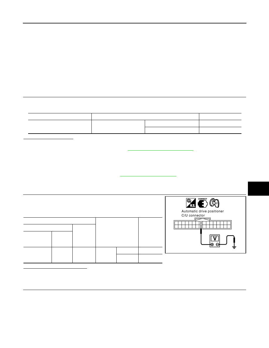
 CHECK PEDAL ADJUSTING SENSOR SIGNAL

1. Turn ignition switch OFF.

2. Check voltage between automatic drive positioner control unit

harness connector and ground. 

Is the inspection result normal?

YES

>> GO TO 4

NO

>> GO TO 2

2.

 CHECK PEDAL ADJUSTING SENSOR CIRCUIT

Monitor item

Condition

Value

PEDAL SEN

Pedal position

Forward

0.5V

Backward

4.5V

Terminal

Condition

Voltage (V)

(Approx.)

(+)

(-)

Automatic 

drive position-

er control unit

Terminal

M33

8

Ground

Pedal as-
sembly 
position

Forward

0.5

Backward

4.5

PIIA4569E

ADP-92

< COMPONENT DIAGNOSIS >

PEDAL ADJUSTING SENSOR

1. Disconect automatic drive positioner control unit and pedal

adjusting motor assembly.

2. Check continuity between automatic drive positioner control unit

harnnes connector and pedal adjusting motor assembly harness

connector.

3. Check continuity between automatic drive positioner control unit

harness connector and ground.

Is the inspection result normal?

YES

>> GO TO 3

NO

>> Repair or replace harness.

3.

 CHECK DOOR MIRROR OPERATION

1. Connect automatic drive positioner control unit and pedal adjusting motor assembly.

2. Turn ignition switch ON.

3. Check door mirror operation with memory function.
Is the operation normal?

YES

>> Replace pedal adjusting motor assembly. Refer to 

ADP-178, "Removal and Installation"

.

NO

>> Replace automatic drive positioner control unit. Refer to 

ADP-175, "Removal and Installation"

.

4.

 CHECK INTERMITTENT INCIDENT

Refer to 

GI-38, "Intermittent Incident"

.

Is the inspection result normal?

YES

>> Replace automatic drive positioner control unit. Refer to 

ADP-175, "Removal and Installation"

.

NO

>> Repair or replace the malfunctioning part.

Automatic drive posi-

tioner

control unit connector

Terminal

Pedal adjusting 

motor assembly 

connector

Terminal

Continuity

M33 (A)

8

E110 (B)

4

Yes

M34 (C)

33

3

41

5

Automatic drive positioner

control unit connector

Terminal

Ground

Continuity 

M33 (A)

8

No

M34 (C)

33

41

ALJIA0327ZZ

MIRROR SENSOR

ADP-93

< COMPONENT DIAGNOSIS >

C

D

E

F

G

H

I

K

L

M

A

B

ADP

N

O

P

MIRROR SENSOR

DRIVER SIDE
DRIVER SIDE : Description

INFOID:0000000005147544

• The mirror sensor LH is installed to the door mirror actuator LH.

• The resistance of 2 sensors (horizontal and vertical) is changed when the door mirror LH is operated.

• Automatic drive positioner control unit calculates the door mirror position according to the change of the volt-

age of 2 sensor input terminals.

DRIVER SIDE : Component Function Check

INFOID:0000000005147545

1.

 CHECK FUNCTION

1. Select “MIR/SEN LH U-D”, “MIR/SEN LH R-L” in “Data monitor” with CONSULT-III.

2. Check mirror sensor (driver side) signal under the following condition.

Is the indication normal?

YES

>> Inspection End.

NO

>> Perform diagnosis procedure. Refer to 

ADP-93, "DRIVER SIDE : Diagnosis Procedure"

.

DRIVER SIDE : Diagnosis Procedure

INFOID:0000000005147546

Regarding Wiring Diagram information, refer to 

ADP-138, "Wiring Diagram"

.

1.

 CHECK DOOR MIRROR LH SENSOR SIGNAL

1. Turn ignition switch to ACC.

2. Check voltage between door mirror LH harness connector and

ground.

Is the inspection result normal?

YES

>> GO TO 5

NO

>> GO TO 2

2.

 CHECK DOOR MIRROR LH SENSOR CIRCUIT 1

Monitor item

Condition

Value

MIR/SEN LH U-D

Door mirror LH

Close to peak

3.4V

Close to valley

0.6V

MIR/SEN LH R-L

Close to right edge

3.4V

Close to left edge

0.6V

Terminals

Condition

Voltage (V)

(Approx.)

(+)

(–)

Door mirror 

LH connector

Terminal

D4

7

Ground

Door 
mirror
LH

Close to peak

3.4

Close to valley

0.6

8

Close to right edge

3.4

Close to left edge

0.6

LIIA1482E

ADP-94

< COMPONENT DIAGNOSIS >

MIRROR SENSOR

1. Turn ignition switch OFF.

2. Disconnect automatic drive positioner control unit and door mir-

ror LH.

3. Check continuity between automatic drive positioner control unit

harness connector and door mirror LH harness connector.

4. Check continuity between automatic drive positioner control unit harness connector and ground.

Is the inspection result normal?

YES

>> GO TO 3

NO

>> Repair or replace harness.

3.

 CHECK DOOR MIRROR LH SENSOR CIRCUIT 2 

1. Check continuity between automatic drive positioner control unit

harness connector and door mirror LH harness connector.

2. Check continuity between automatic drive positioner control unit

harness connector and ground.

Is the inspection result normal?

YES

>> GO TO 4

NO

>> Repair or replace harness.

4.

 CHECK PEDAL ADJUSTING OPERATION

1. Connect driver seat control unit and door mirror LH.

2. Turn ignition switch ON.

3. Check pedal adjusting operation with memory function.
Is the operation normal?

YES

>> Replace door mirror actuator LH. Refer to 

MIR-19, "Mirror Actuator"

.

NO

>> Replace automatic drive positioner control unit. Refer to 

ADP-175, "Removal and Installation"

.

5.

 CHECK INTERMITTENT INCIDENT

Refer to 

GI-38, "Intermittent Incident"

.

Is the inspection result normal?

YES

>> Replace automatic drive positioner control unit. Refer to 

ADP-175, "Removal and Installation"

.

NO

>> Repair or replace the malfunctioning part.

Automatic drive 

positioner control 

unit connector

Terminal

Door mirror LH 

connector

Terminal

Continuity

M33

6

D4

7

Yes

22

8

Automatic drive positioner

 control unit connector

Terminal

Ground

Continuity 

M33

6

No

22

LIIA1484E

Automatic drive 

positioner control 

unit connector

Terminal

Door mirror LH 

connector

Terminal

Continuity

M34

33

D4

5

Yes

41

6

Automatic drive positioner

 control unit connector

Terminal

Ground

Continuity 

M34

33

No

41

LIIA1483E


Content   ..  23  24  25  26   ..