Infiniti QX56 (Z62). Manual - part 936
MIR-36
< REMOVAL AND INSTALLATION >
OUTSIDE MIRROR
DOOR MIRROR COVER : Removal and Installation
INFOID:0000000006257240
CAUTION:
Never damage the mirror bodies.
REMOVAL
1.
Remove the glass mirror. Refer to
MIR-35, "GLASS MIRROR : Removal and Installation"
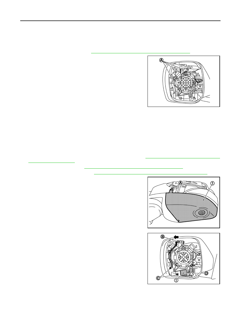
2.
Remove the pawls (A), and disassemble door mirror cover from
door mirror assembly.
INSTALLATION
Note the following item, and then install in the reverse order of removal.
CAUTION:
After installation, visually check that all the pawls are securely engaged.
SIDE CAMERA FINISHER ASSEMBLY
SIDE CAMERA FINISHER ASSEMBLY : Removal and Installation
INFOID:0000000006257241
Disassembly
1.
Remove door mirror assembly from front door panel. Refer to
MIR-32, "DOOR MIRROR ASSEMBLY :
.
2.
Remove glass mirror. Refer to
MIR-35, "GLASS MIRROR : Removal and Installation"
.
3.
Remove door mirror cover. Refer to
MIR-36, "DOOR MIRROR COVER : Removal and Installation"
4.
Remove side camera finisher (1) fixing screw (A).
5.
Disconnect harness connector (B), and remove screws (C) and
pawl (D) fixing the side camera finisher (1) to housing.
JMLIA1145ZZ
JMLIA0912ZZ
JMLIA0921ZZ