Infiniti QX56 (Z62). Manual - part 848


  Index      Infiniti     Infiniti QX56 (Z62) - service repair manual 2011 year


Search            


Content   ..  846  847  848  849   ..


Infiniti QX56 (Z62). Manual - part 848


INT-40

< REMOVAL AND INSTALLATION >

BACK DOOR TRIM

2.

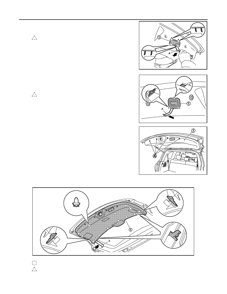
Disengage pull handle finisher (1) fixing pawls using a remover
tool (A), and then remove pull handle finisher.

3.

Disengage auto back door switch finisher (1) fixing pawls using
a remover tool (A), and then disconnect auto back door switch
harness connector.

4.

Remove back door finisher inner lower (1) fixing clips (A).

5.

Remove the back door finisher inner lower.
1.

Disengage back door finisher inner lower (1) fixing clips and pawls using a remover tool (A).

NOTE:
Start disengaging from the position where pawls are located as shown in the figure.

: Pawl

JMJIA4048ZZ

: Pawl

JMJIA4049ZZ

JMJIA4047ZZ

: Clip

: Pawl

JMJIA4050ZZ

BACK DOOR TRIM

INT-41

< REMOVAL AND INSTALLATION >

C

D

E

F

G

H

I

K

L

M

A

B

INT

N

O

P

2.

Remove back door finisher inner lower.

6.

Disengage back door finisher side (1) fixing metal clips using a
remover tool (A), and then remove back door finisher side.

7.

Disengage back door finisher upper (1) fixing metal clips using a
remover tool (A), and then remove back door finisher upper.

INSTALLATION

Note the following items, and install in the reverse order of removal.

CAUTION:

• Visually check the clips, pawls and metal clips for deformation and damage during installation.

Replace with new ones if necessary.

• When installing back door trims, check that clips, pawls, and metal clips are securely fitted in body

panel holes, and press them in.

: Metal clip

JMJIA4052ZZ

: Metal clip

JMJIA4051ZZ

IP-1

BODY INTERIOR

C

D

E

F

G

H

I

K

L

M

SECTION 

IP

A

B

IP

N

O

P

CONTENTS

INSTRUMENT PANEL

PRECAUTION ...............................................

2

PRECAUTIONS ...................................................

2

Precaution for Supplemental Restraint System 
(SRS) "AIR BAG" and "SEAT BELT PRE-TEN-
SIONER" .................................................................
..

2

Precaution Necessary for Steering Wheel Rota-
tion after Battery Disconnect  ...................................
..

2

Service ......................................................................

3

PREPARATION ............................................

4

PREPARATION ...................................................

4

Special Service Tools ..............................................

4

Commercial Service Tools .......................................

4

CLIP LIST  ............................................................

6

Clip List  .....................................................................

6

SYMPTOM DIAGNOSIS  ...............................

7

SQUEAK AND RATTLE TROUBLE DIAG-
NOSES ...............................................................

7

Work Flow .................................................................

7

Inspection Procedure ................................................

9

Diagnostic Worksheet ..............................................

11

REMOVAL AND INSTALLATION  ...............

13

INSTRUMENT PANEL ASSEMBLY  .................

13

Exploded View .........................................................

13

Removal and Installation  .........................................

14

CENTER CONSOLE ASSEMBLY  ....................

23

Exploded View .........................................................

23

Removal and Installation  .........................................

25

Disassembly and Assembly .....................................

27

REAR CONSOLE ASSEMBLY  .........................

29

Exploded View .........................................................

29

Removal and Installation  .........................................

29

Disassembly and Assembly .....................................

30

IP-2

< PRECAUTION >

PRECAUTIONS

PRECAUTION

PRECAUTIONS

Precaution for Supplemental Restraint System (SRS) "AIR BAG" and "SEAT BELT 
PRE-TENSIONER"

INFOID:0000000006113088

The Supplemental Restraint System such as “AIR BAG” and “SEAT BELT PRE-TENSIONER”, used along
with a front seat belt, helps to reduce the risk or severity of injury to the driver and front passenger for certain
types of collision. This system includes seat belt switch inputs and dual stage front air bag modules. The SRS
system uses the seat belt switches to determine the front air bag deployment, and may only deploy one front
air bag, depending on the severity of a collision and whether the front occupants are belted or unbelted.
Information necessary to service the system safely is included in the “SRS AIR BAG” and “SEAT BELT” of this
Service Manual.

WARNING:

• To avoid rendering the SRS inoperative, which could increase the risk of personal injury or death in

the event of a collision that would result in air bag inflation, all maintenance must be performed by
an authorized NISSAN/INFINITI dealer.

• Improper maintenance, including incorrect removal and installation of the SRS, can lead to personal

injury caused by unintentional activation of the system. For removal of Spiral Cable and Air Bag
Module, see the “SRS AIR BAG”.

• Do not use electrical test equipment on any circuit related to the SRS unless instructed to in this

Service Manual. SRS wiring harnesses can be identified by yellow and/or orange harnesses or har-
ness connectors.

PRECAUTIONS WHEN USING POWER TOOLS (AIR OR ELECTRIC) AND HAMMERS

WARNING:

• When working near the Air Bag Diagnosis Sensor Unit or other Air Bag System sensors with the

ignition ON or engine running, DO NOT use air or electric power tools or strike near the sensor(s)
with a hammer. Heavy vibration could activate the sensor(s) and deploy the air bag(s), possibly
causing serious injury.

• When using air or electric power tools or hammers, always switch the ignition OFF, disconnect the

battery, and wait at least 3 minutes before performing any service.

Precaution Necessary for Steering Wheel Rotation after Battery Disconnect

INFOID:0000000006113089

NOTE:
• Before removing and installing any control units, first turn the push-button ignition switch to the LOCK posi-

tion, then disconnect both battery cables.

• After finishing work, confirm that all control unit connectors are connected properly, then re-connect both

battery cables.

• Always use CONSULT-III to perform self-diagnosis as a part of each function inspection after finishing work.

If a DTC is detected, perform trouble diagnosis according to self-diagnosis results.

For vehicle with steering lock unit, if the battery is disconnected or discharged, the steering wheel will lock and
cannot be turned.
If turning the steering wheel is required with the battery disconnected or discharged, follow the operation pro-
cedure below before starting the repair operation.

OPERATION PROCEDURE

1.

Connect both battery cables.
NOTE:
Supply power using jumper cables if battery is discharged.

2.

Turn the push-button ignition switch to ACC position.
(At this time, the steering lock will be released.)

3.

Disconnect both battery cables. The steering lock will remain released with both battery cables discon-
nected and the steering wheel can be turned.

4.

Perform the necessary repair operation.


Content   ..  846  847  848  849   ..