Infiniti QX56 (Z62). Manual - part 748


  Index      Infiniti     Infiniti QX56 (Z62) - service repair manual 2011 year


Search            


Content   ..  746  747  748  749   ..


Infiniti QX56 (Z62). Manual - part 748


IDENTIFICATION INFORMATION

GI-25

< VEHICLE INFORMATION >

C

D

E

F

G

H

I

J

K

L

M

B

GI

N

O

P

Dimensions

INFOID:0000000006280863

Unit: mm (in)

Wheels & Tires

INFOID:0000000006280864
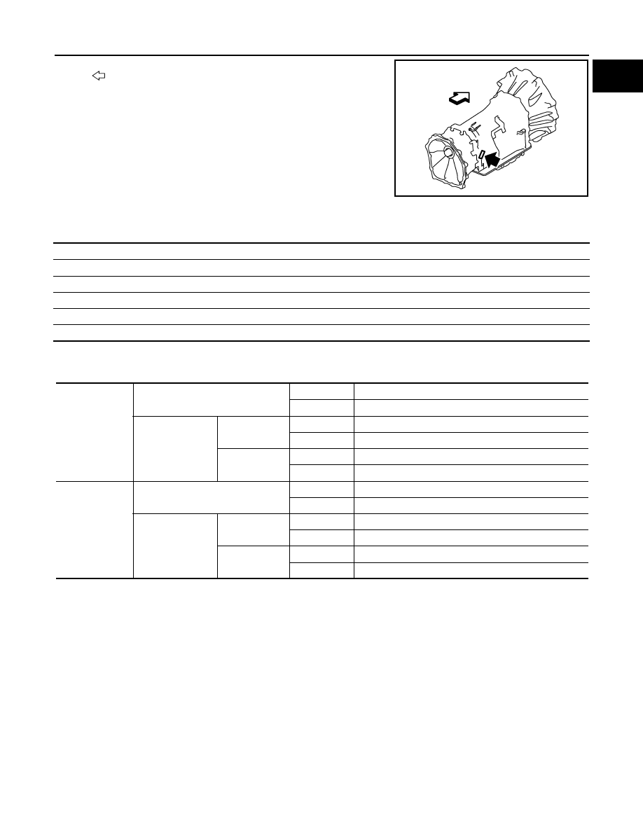
: Vehicle front

JPAIA0770ZZ

Overall length

5,290 (208.3)

Overall width

2,030 (79.9)

Overall height

1,925 (75.8)

Front tread

1,715 (67.5)

Rear tread

1,725 (67.9)

Wheelbase

3,075 (121.1)

Conventional

Tire

20 inch

P275/60R20 114H

22 inch

P275/50R22 111H

Road wheel

20 inch
(Aluminum)

Size

20 

×

 8J

Offset

30 mm (1.18 in)

22 inch
(Aluminum)

Size

22 

×

 8J

Offset

30 mm (1.18 in)

Spare

Tire

20 inch

P275/60R20 114H

22 inch

P275/50R22 111H

Road wheel

20 inch
(Aluminum)

Size

20 

×

 8J

Offset

30 mm (1.18 in)

22 inch
(Aluminum)

Size

22 

×

 8J

Offset

30 mm (1.18 in)

GI-26

< PRECAUTION >

PRECAUTIONS

PRECAUTION

PRECAUTIONS

Description

INFOID:0000000006280865

Observe the following precautions to ensure safe and proper servicing. These precautions are not
described in each individual section.

Precaution for Supplemental Restraint System (SRS) "AIR BAG" and "SEAT BELT 
PRE-TENSIONER"

INFOID:0000000006280866

The Supplemental Restraint System such as “AIR BAG” and “SEAT BELT PRE-TENSIONER”, used along
with a front seat belt, helps to reduce the risk or severity of injury to the driver and front passenger for certain
types of collision. This system includes seat belt switch inputs and dual stage front air bag modules. The SRS
system uses the seat belt switches to determine the front air bag deployment, and may only deploy one front
air bag, depending on the severity of a collision and whether the front occupants are belted or unbelted.
Information necessary to service the system safely is included in the “SRS AIR BAG” and “SEAT BELT” of this
Service Manual.

WARNING:

• To avoid rendering the SRS inoperative, which could increase the risk of personal injury or death in

the event of a collision that would result in air bag inflation, all maintenance must be performed by
an authorized NISSAN/INFINITI dealer.

• Improper maintenance, including incorrect removal and installation of the SRS, can lead to personal

injury caused by unintentional activation of the system. For removal of Spiral Cable and Air Bag
Module, see the “SRS AIR BAG”.

• Do not use electrical test equipment on any circuit related to the SRS unless instructed to in this

Service Manual. SRS wiring harnesses can be identified by yellow and/or orange harnesses or har-
ness connectors.

PRECAUTIONS WHEN USING POWER TOOLS (AIR OR ELECTRIC) AND HAMMERS

WARNING:

• When working near the Air Bag Diagnosis Sensor Unit or other Air Bag System sensors with the

ignition ON or engine running, DO NOT use air or electric power tools or strike near the sensor(s)
with a hammer. Heavy vibration could activate the sensor(s) and deploy the air bag(s), possibly
causing serious injury.

• When using air or electric power tools or hammers, always switch the ignition OFF, disconnect the

battery, and wait at least 3 minutes before performing any service.

Precautions For Xenon Headlamp Service

INFOID:0000000006280867

WARNING:

Comply with the following warnings to prevent any serious accident.
• Disconnect the battery cable (negative terminal) or the power supply fuse before installing, remov-

ing, or touching the xenon headlamp (bulb included). The xenon headlamp contains high-voltage
generated parts.

• Never work with wet hands.
• Check the xenon headlamp ON-OFF status after assembling it to the vehicle. Never turn the xenon

headlamp ON in other conditions. Connect the power supply to the vehicle-side connector.
(Turning it ON outside the lamp case may cause fire or visual impairments.)

• Never touch the bulb glass immediately after turning it OFF. It is extremely hot. 

CAUTION:

Comply with the following cautions to prevent any error and malfunction.
• Install the xenon bulb securely. (Insufficient bulb socket installation may melt the bulb, the connec-

tor, the housing, etc. by high-voltage leakage or corona discharge.)

• Never perform HID circuit inspection with a tester.
• Never touch the xenon bulb glass with hands. Never put oil and grease on it.
• Dispose of the used xenon bulb after packing it in thick vinyl without breaking it. 
• Never wipe out dirt and contamination with organic solvent (thinner, gasoline, etc.).

PRECAUTIONS

GI-27

< PRECAUTION >

C

D

E

F

G

H

I

J

K

L

M

B

GI

N

O

P

Precaution Necessary for Steering Wheel Rotation after Battery Disconnect

INFOID:0000000006280868

NOTE:
• Before removing and installing any control units, first turn the push-button ignition switch to the LOCK posi-

tion, then disconnect both battery cables.

• After finishing work, confirm that all control unit connectors are connected properly, then re-connect both

battery cables.

• Always use CONSULT-III to perform self-diagnosis as a part of each function inspection after finishing work.

If a DTC is detected, perform trouble diagnosis according to self-diagnosis results.

For vehicle with steering lock unit, if the battery is disconnected or discharged, the steering wheel will lock and
cannot be turned.
If turning the steering wheel is required with the battery disconnected or discharged, follow the operation pro-
cedure below before starting the repair operation.

OPERATION PROCEDURE

1.

Connect both battery cables.
NOTE:
Supply power using jumper cables if battery is discharged.

2.

Turn the push-button ignition switch to ACC position.
(At this time, the steering lock will be released.)

3.

Disconnect both battery cables. The steering lock will remain released with both battery cables discon-
nected and the steering wheel can be turned.

4.

Perform the necessary repair operation.

5.

When the repair work is completed, re-connect both battery cables. With the brake pedal released, turn
the push-button ignition switch from ACC position to ON position, then to LOCK position. (The steering
wheel will lock when the push-button ignition switch is turned to LOCK position.)

6.

Perform self-diagnosis check of all control units using CONSULT-III.

Precaution for Procedure without Cowl Top Cover

INFOID:0000000006280869

When performing the procedure after removing cowl top cover, cover
the lower end of windshield with urethane, etc.

General Precautions

INFOID:0000000006280870

• Do not operate the engine for an extended period of time without

proper exhaust ventilation.
Keep the work area well ventilated and free of any inflammable
materials. Special care should be taken when handling any inflam-
mable or poisonous materials, such as gasoline, refrigerant gas,
etc. When working in a pit or other enclosed area, be sure to prop-
erly ventilate the area before working with hazardous materials.
Do not smoke while working on the vehicle.

PIIB3706J

SGI285

GI-28

< PRECAUTION >

PRECAUTIONS

• Before jacking up the vehicle, apply wheel chocks or other tire

blocks to the wheels to prevent the vehicle from moving. After jack-
ing up the vehicle, support the vehicle weight with safety stands at
the points designated for proper lifting before working on the vehi-
cle.
These operations should be done on a level surface.

• When removing a heavy component such as the engine or tran-

saxle/transmission, be careful not to lose your balance and drop
them. Also, do not allow them to strike adjacent parts, especially
the brake tubes and master cylinder.

• Before starting repairs which do not require battery power:

Turn off ignition switch.
Disconnect the negative battery terminal.

• If the battery terminals are disconnected, recorded memory of

radio and each control unit is erased.

• To prevent serious burns:

Avoid contact with hot metal parts.
Do not remove the radiator cap when the engine is hot.

• Dispose of drained oil or the solvent used for cleaning parts in an

appropriate manner.

• Do not attempt to top off the fuel tank after the fuel pump nozzle

shuts off automatically.
Continued refueling may cause fuel overflow, resulting in fuel spray
and possibly a fire.

• Clean all disassembled parts in the designated liquid or solvent

prior to inspection or assembly.

• Replace oil seals, gaskets, packings, O-rings, locking washers,

cotter pins, self-locking nuts, etc. with new ones.

• Replace inner and outer races of tapered roller bearings and needle bearings as a set.
• Arrange the disassembled parts in accordance with their assembled locations and sequence.
• Do not touch the terminals of electrical components which use microcomputers (such as ECM).

Static electricity may damage internal electronic components.

• After disconnecting vacuum or air hoses, attach a tag to indicate the proper connection.
• Use only the fluids and lubricants specified in this manual.
• Use approved bonding agent, sealants or their equivalents when required.
• Use hand tools, power tools (disassembly only) and recommended

special tools where specified for safe and efficient service repairs.

• When repairing the fuel, oil, water, vacuum or exhaust systems,

check all affected lines for leakage.

SGI231

SEF289H

SGI233

JPAIA0335ZZ


Content   ..  746  747  748  749   ..