Infiniti QX56 (Z62). Manual - part 699


  Index      Infiniti     Infiniti QX56 (Z62) - service repair manual 2011 year


Search            


Content   ..  697  698  699  700   ..


Infiniti QX56 (Z62). Manual - part 699


EXL-88

< DTC/CIRCUIT DIAGNOSIS >

[XENON TYPE]

HEADLAMP (LO) CIRCUIT

HEADLAMP (LO) CIRCUIT

Component Function Check

INFOID:0000000006213957

1.

CHECK HEADLAMP (LO) OPERATION

CONSULT-III ACTIVE TEST

1.

Select “EXTERNAL LAMPS” of IPDM E/R active test item.

2.

With operating the test items, check that the headlamp (LO) is turned ON.

Is the inspection result normal?

YES

>> Headlamp (LO) is normal.

NO

>> Refer to 

EXL-88, "Diagnosis Procedure"

.

Diagnosis Procedure

INFOID:0000000006213958

1.

CHECK HEADLAMP (LO) OUTPUT VOLTAGE

CONSULT-III ACTIVE TEST

1.

Turn ignition switch OFF.

2.

Disconnect front combination lamp connector.

3.

Turn ignition switch ON.

4.

Select “EXTERNAL LAMPS” of IPDM E/R active test item.

5.

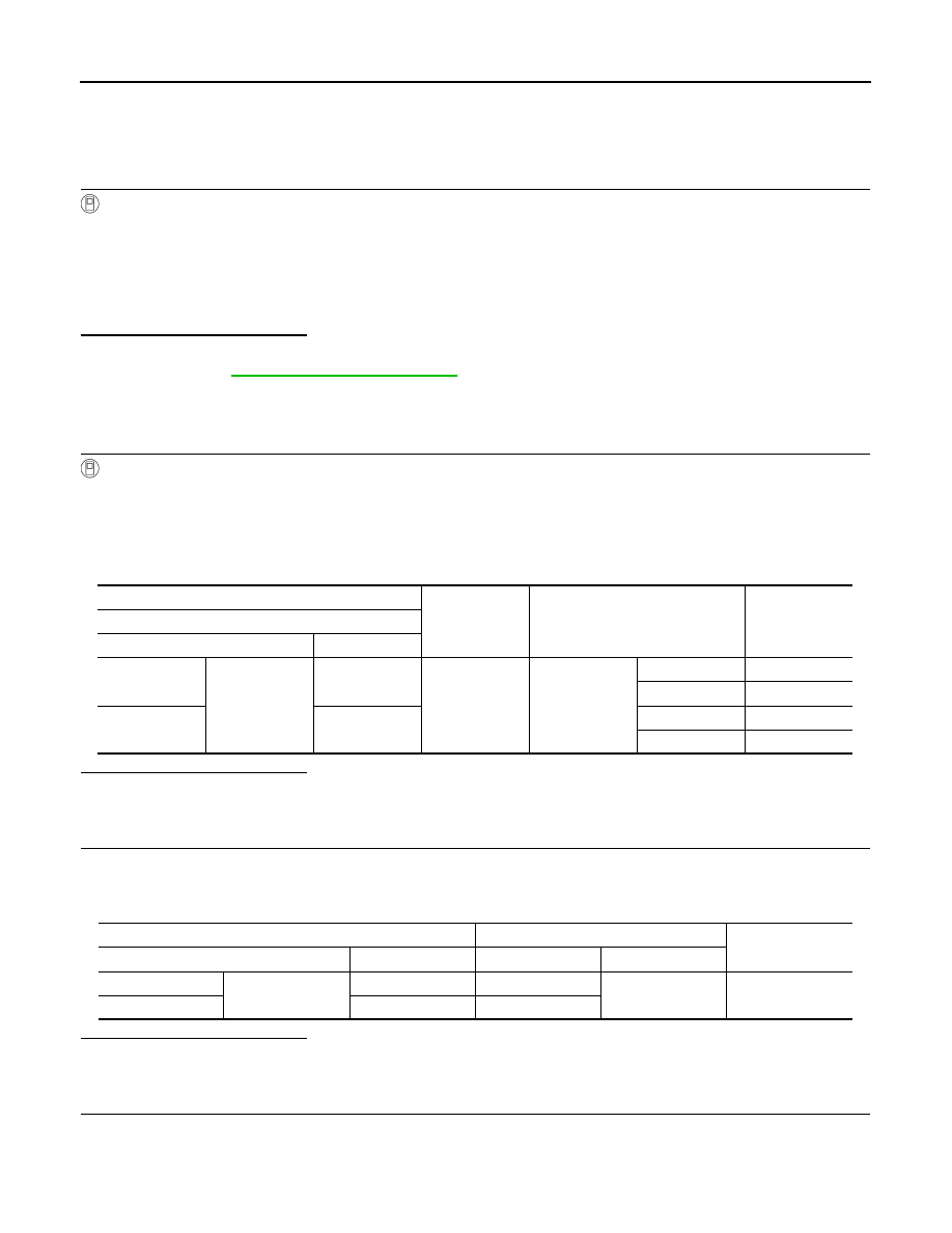
With operating the test items, check voltage between IPDM E/R harness connector and ground.

Is the inspection result normal?

YES

>> GO TO 2.

NO

>> GO TO 3.

2.

CHECK HEADLAMP (LO) OPEN CIRCUIT

1.

Turn ignition switch OFF.

2.

Disconnect IPDM E/R connector.

3.

Check continuity between IPDM E/R harness connector and front combination lamp harness connector.

Is the inspection result normal?

YES

>> GO TO 5.

NO

>> Repair or replace harness.

3.

CHECK HEADLAMP (LO) FUSE

1.

Turn ignition switch OFF.

2.

Check that the following fuses are not fusing.

Lo

: Headlamp (LO) ON

Off

: Headlamp (LO) OFF

(+)

(

)

Test item

Voltage

(Approx.)

IPDM E/R

Connector

Terminal

RH

E15

52

Ground

EXTERNAL 
LAMPS

Lo

Battery voltage

Off

0 V

LH

51

Lo

Battery voltage

Off

0 V

IPDM E/R

Front combination lamp

Continuity

Connector

Terminal

Connector

Terminal

RH

E15

52

E119

5

Existed

LH

51

E118

HEADLAMP (LO) CIRCUIT

EXL-89

< DTC/CIRCUIT DIAGNOSIS >

[XENON TYPE]

C

D

E

F

G

H

I

J

K

M

A

B

EXL

N

O

P

Is the inspection result normal?

YES

>> Replace IPDM E/R.

NO

>> GO TO 4.

4.

CHECK HEADLAMP (LO) SHORT CIRCUIT

1.

Disconnect IPDM E/R connector.

2.

Check continuity between IPDM E/R harness connector and ground.

Is the inspection result normal?

YES

>> Replace fuse. (Replace IPDM E/R if the fuse is fusing again.)

NO

>> Repair or replace harness. And then replace the fuse.

5.

CHECK HEADLAMP (LO) GROUND OPEN CIRCUIT

1.

Turn ignition switch OFF.

2.

Disconnect front combination lamp connector.

3.

Check continuity between front combination lamp harness connector and ground.

Is the inspection result normal?

YES

>> Perform the xenon headlamp diagnosis. Refer to 

EXL-90, "Diagnosis Procedure"

.

NO

>> Repair or replace harness.

Unit

Lotion

Fuse No.

Capacity

Headlamp LO (RH) 

IPDM E/R

#54

15 A

Headlamp LO (LH) 

#53

IPDM E/R

Ground

Continuity

Connector

Terminal

RH

E15

52

Not existed

LH

51

Front combination lamp

Ground

Continuity

Connector

Terminal

RH

E119

1

Existed

LH

E118

EXL-90

< DTC/CIRCUIT DIAGNOSIS >

[XENON TYPE]

XENON HEADLAMP

XENON HEADLAMP

Diagnosis Procedure

INFOID:0000000006213959

1.

CHECK XENON BULB

Install the normal bulb to the applicable headlamp. Turn the lighting switch ON.
Is the headlamp turned ON?

YES

>> Replace xenon bulb.

NO

>> GO TO 2.

2.

CHECK HID CONTROL UNIT

Install the normal HID control unit to the applicable headlamp. Turn the lighting switch ON
Is the headlamp turned ON?

YES

>> Replace HID control unit. 

NO

>> Xenon headlamp is normal. Check headlamp control system.

HEADLAMP LEVELIZER CIRCUIT

EXL-91

< DTC/CIRCUIT DIAGNOSIS >

[XENON TYPE]

C

D

E

F

G

H

I

J

K

M

A

B

EXL

N

O

P

HEADLAMP LEVELIZER CIRCUIT

Component Function Check

INFOID:0000000006213960

1.

CHECK AIMING MOTOR OPERATION

CONSULT-III ACTIVE TEST

1.

Start the engine.

2.

Turn the lighting switch 2ND.

3.

Select “LEVELIZER TEST” of ADAPTIVE LIGHT active test item.

4.

With operating the test item, check the operation.

Is the operation normal?

YES

>> Headlamp levelizer circuit is normal.

NO

>> Refer to 

EXL-91, "Diagnosis Procedure"

.

Diagnosis Procedure

INFOID:0000000006213961

1.

CHECK AIMING MOTOR DRIVE SIGNAL OUTPUT

CONSULT-III ACTIVE TEST

1.

Start the engine. 

2.

Turn light switch 2ND.

3.

Select “LEVELIZER TEST” of ADAPTIVE LIGHT active test item.

4.

With operating the test item, check voltage between AFS control unit harness connector and ground.

Is the inspection result normal?

YES

>> GO TO 2.

NO

>> GO TO 3.

2.

CHECK AIMING MOTOR DRIVE SIGNAL OPEN CIRCUIT

1.

Turn ignition switch OFF.

2.

Disconnect AFS control unit connector and headlamp aiming motor connector.

3.

Check continuity between AFS control unit harness connector and head lamp aiming motor harness con-
nector.

Is the inspection result normal?

YES

>> Replace front combination lamp.

NO

>> Repair or replace harness.

Test item

Optical axis

LEVELIZER TEST

Origin

Standard positon

Peak

Lowest position

(+)

(

)

Test item

Voltage

(Approx.)

AFS control unit

Connector

Terminal

RH

M135

19

Ground

LEVELIZER TEST

Origin

7.5 V

Peak

7.3 V

LH

40

Origin

7.5 V

Peak

7.3 V

AFS control unit

Headlamp aiming motor

Continuity

Connector

Terminal

Connector

Terminal

RH

M135

19

E121

1

Existed

LH

40

E120


Content   ..  697  698  699  700   ..