Infiniti QX56 (Z62). Manual - part 679


  Index      Infiniti     Infiniti QX56 (Z62) - service repair manual 2011 year


Search            


Content   ..  677  678  679  680   ..


Infiniti QX56 (Z62). Manual - part 679


EXL-8

< SYSTEM DESCRIPTION >

[XENON TYPE]

COMPONENT PARTS

*1: With AFS system models

*

2

: With headlamp aiming control system (manual) models

FRONT COMBINATION LAMP

FRONT COMBINATION LAMP : Xenon Headlamp

INFOID:0000000006213889

OUTLINE

• The lamp light source is by the arch discharge by applying high voltage into the xenon gas-filled bulb instead

of the halogen bulb filament. 

• Sight becomes more natural and brighter because the amount of light are gained adequately and the color of

light is sunshine-like white. 

• The xenon bulb drops the amount of light, repeats blinking, and illuminates in red if the bulb reaches the ser-

vice life.

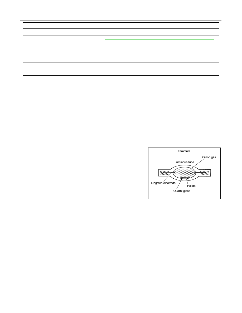
ILLUMINATION PRINCIPLE

1.

 Discharging starts in high voltage pulse between bulb elec-
trodes.

2.

Xenon gas is activated by current between electrodes. Pale light
is emitted.

3.

The luminous tube (bulb) temperature elevates. Evaporated
halide is activated by discharge. The color of light changes into
white.

NOTE:
• Brightness and the color of light may change slightly immediately

after the headlamp turned ON until the xenon bulb becomes sta-
ble. This is not malfunction.

• Illumination time lag may occur between right and left. This is not

malfunction.

PRECAUTIONS FOR TROUBLE DIAGNOSIS

Representative malfunction examples are; "Light does not turn ON", "Light blinks", and "Brightness is inade-
quate." The cause often be the xenon bulb. Such malfunctions, however, are occurred occasionally by HID
control unit malfunction or lamp case malfunction. Specify the malfunctioning part with diagnosis procedure. 

WARNING:

• Never touch the harness, HID control unit, the inside and metal part of lamp when turning the head-

lamp ON or operating the lighting switch. 

• Never work with wet hands.

CAUTION:

• Never perform HID control unit circuit diagnosis with a circuit tester or an equivalent.
• Temporarily install the headlamps on the vehicle. Connect the battery to the connector (vehicle side)

when checking ON/OFF status.

• Disconnect the battery negative terminal before disconnecting the lamp socket connector or the har-

ness connector.

• Check for fusing of the fusible link(s), open around connector, short, disconnection if the symptom

is caused by electric error.

NOTE:
• Turn the switch OFF once before turning ON, if the ON/OFF is inoperative.
• The xenon bulb drops the amount of light, repeats blinking, and illuminates in red if the bulb reaches the ser-

vice life.

Steering angle sensor*

1

Transmits steering angle sensor signal to AFS control unit. (via CAN communication)

Combination switch
(Lighting & turn signal switch)

Refer to 

BCS-7, "COMBINATION SWITCH READING SYSTEM : System Descrip-

tion"

.

Door switch

Inputs the door switch signal to BCM.

AFS switch*

1

• Inputs the AFS switch signal to AFS control unit.
• AFS switch is integrated in triple switch.

Headlamp aiming switch*

2

Outputs the aiming motor drive signal to aiming motor.

Hazard switch

Inputs the hazard switch signal to BCM.

Part

Description

JPLIA0421GB

COMPONENT PARTS

EXL-9

< SYSTEM DESCRIPTION >

[XENON TYPE]

C

D

E

F

G

H

I

J

K

M

A

B

EXL

N

O

P

FRONT COMBINATION LAMP : HID control unit

INFOID:0000000006213890

Headlamp (LO) circuit is connected to HID control unit integrated in the headlamp. Headlamp (LO) circuit turns
xenon headlamp ON.
For the details of HID control unit and the xenon headlamp, refer to 

EXL-8, "FRONT COMBINATION LAMP :

Xenon Headlamp"

.

FRONT COMBINATION LAMP : High Beam Solenoid

INFOID:0000000006213891

The high beam solenoid drives the mobile valve shade. And the mobile valve shade switches the high beam
and low beam of headlamp.
• When the headlamp high relay is turned ON, magnetic force is

applied to the high beam solenoid (1) by a current. The mobile
valve shade (2) is switched to the high beam position.

• When the headlamp high relay is turned OFF, the current stops.

The mobile valve shade returns to the low beam position automati-
cally.

FRONT COMBINATION LAMP : Aiming Motor

INFOID:0000000006213892

The headlamp levelizer adjusts the headlamp light axis upward and downward with the aiming motor inte-
grated in the front combination lamp.

FRONT COMBINATION LAMP : Swivel Actuator

INFOID:0000000006213893

SWIVEL ACTUATOR

The swivel actuator is installed in the headlamp unit. The swivel actuator consists of the swivel motor and the
swivel position sensor.

SWIVEL MOTOR

• The swivel motor is the two-phase step motor.
• The swivel motor drives headlamp by exciting the two drive coils according to the drive signal from AFS con-

trol unit. 

• The rotation direction of the swivel motor is changeable by changing the exciting pattern. 

SWIVEL POSITION SENSOR

The swivel position sensor detects the headlamp swivel angle to transmit the swivel position sensor signal to
AFS control unit.

JSLIA0129ZZ

EXL-10

< SYSTEM DESCRIPTION >

[XENON TYPE]

SYSTEM

SYSTEM

HEADLAMP SYSTEM

HEADLAMP SYSTEM : System Diagram

INFOID:0000000006213894

HEADLAMP SYSTEM : System Description

INFOID:0000000006213895

OUTLINE

Headlamp is controlled by combination switch reading function and headlamp control function of BCM, and
relay control function of IPDM E/R.

HEADLAMP (LO) OPERATION 

• BCM detects the combination switch condition with the combination switch reading function.
• BCM transmits the low beam request signal to IPDM E/R via CAN communication according to the head-

lamp (LO) ON condition.

Headlamp (LO) ON condition

- Lighting switch 2ND
- Lighting switch AUTO (auto light function ON judgment)
- Lighting switch AUTO, with the front fog lamp switch ON and the ignition switch ON 
- Lighting switch PASS
• IPDM E/R turns the integrated headlamp low relay ON, and turns the headlamp ON according to the low

beam request signal.

HEADLAMP (HI) OPERATION

• BCM transmits the high beam request signal to IPDM E/R and the combination meter via CAN communica-

tion according to the headlamp (HI) ON condition. 

Headlamp (HI) ON condition

- Lighting switch HI with the lighting switch 2ND or AUTO (auto light function ON judgment)
- Lighting switch PASS
- Lighting switch AUTO, with the front fog lamp switch ON, the ignition switch ON and lighting switch HI
• Combination meter turns the high beam indicator lamp ON according to the high beam request signal. 
• IPDM E/R turns the integrated headlamp high relay ON, and turns the headlamp ON according to the high

beam request signal.

HEADLAMP SYSTEM : Fail-safe

INFOID:0000000006213896

CAN COMMUNICATION CONTROL

When CAN communication with BCM is impossible, IPDM E/R performs fail-safe control. After CAN communi-
cation recovers normally, it also returns to normal control.

If No CAN Communication Is Available With BCM

JMLIA1083GB

SYSTEM

EXL-11

< SYSTEM DESCRIPTION >

[XENON TYPE]

C

D

E

F

G

H

I

J

K

M

A

B

EXL

N

O

P

*: With daytime running light system

AUTO LIGHT SYSTEM

AUTO LIGHT SYSTEM : System Diagram

INFOID:0000000006213897

AUTO LIGHT SYSTEM : System Description (For CANADA)

INFOID:0000000006218912

OUTLINE

•  Auto light system is controlled by each function of BCM and IPDM E/R.

Control by BCM

- Combination switch reading function
- Headlamp control function
- Auto light function
- Delay timer function
- Wiper linked auto lighting function
- Auto light adjustment system

Control by IPDM E/R

- Relay control function
• Auto light system has the auto light function, wiper linked auto lighting function and delay timer function.
- Auto light function automatically turns ON/OFF the exterior lamps* and each illumination automatically,

depending on the outside brightness.

- Wiper linked auto lighting function automatically turns ON/OFF the exterior lamps* and each illumination

when the light switch is in the AUTO position, according to a front wiper operation.

- When auto light system turns the exterior lamps ON with the ignition switch OFF, delay timer function turns

the exterior lamps OFF, depending on the vehicle condition with the auto light function after a certain period
of time.

*: Headlamp (LO/HI), parking lamp, side marker lamp, tail lamp and front fog lamp (Headlamp HI and front fog
lamp depend on the combination switch condition.)

AUTO LIGHT FUNCTION

• BCM detects the combination switch condition with the combination switch reading function.
• BCM supplies voltage to optical sensor when the ignition switch is turned ON or ACC.
• Optical sensor converts outside brightness (lux) to voltage and transmits the optical sensor signal to BCM.
• BCM judges outside brightness from the optical sensor signal and judges ON/OFF condition of the exterior

lamp and each illumination according to the outside brightness. 

Control part

Fail-safe operation

Headlamp

• Turns ON the headlamp low relay when the ignition switch is turned ON
• Turns OFF the headlamp low relay when the ignition switch is turned OFF
• Headlamp high relay OFF

JMLIA1254GB


Content   ..  677  678  679  680   ..