Infiniti QX56 (Z62). Manual - part 631


  Index      Infiniti     Infiniti QX56 (Z62) - service repair manual 2011 year


Search            


Content   ..  629  630  631  632   ..


Infiniti QX56 (Z62). Manual - part 631


EC-502

< DTC/CIRCUIT DIAGNOSIS >

[VK56VD]

HIGH PRESSURE FUEL PUMP

4.

Also check harness for short to ground and to power.

Is inspection result normal?

YES

>> GO TO 2.

NO

>> Repair or replace error-detected parts.

2.

CHECK HIGH PRESSURE FUEL PUMP SOLENOID

Refer to 

EC-502, "Component Inspection"

.

Is inspection result normal?

YES

>> GO TO 3.

NO

>> Replace high pressure fuel pump. Refer to 

EM-43, "Removal and Installation"

.

3.

CHECK HIGH PRESSURE FUEL PUMP INSTALLATION CONDITION

1.

Turn ignition switch OFF.

2.

Check that the high pressure fuel pump is installed with no backlash and looseness.

Is the inspection result normal?

YES

>> GO TO 4.

NO

>> Repair or replace error-detected parts.

4.

CHECK CAMSHAFT

1.

Remove camshaft. Refer to 

EM-75, "Removal and Installation"

.

2.

Check camshaft. Refer to 

EM-77, "Inspection"

.

Is inspection result normal?

YES

>> INSPECTION END

NO

>> Replace camshaft. Refer to 

EM-75, "Removal and Installation"

.

Component Inspection

INFOID:0000000006218007

1.

CHECK HIGH PRESSURE FUEL PUMP SOLENOID

1.

Turn ignition switch OFF.

2.

Disconnect high pressure fuel pump harness connector.

3.

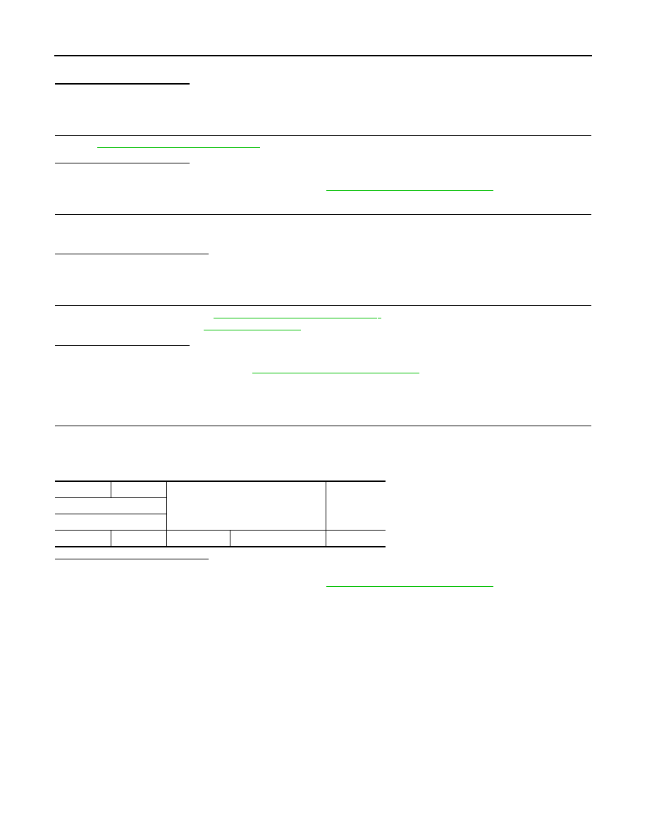
Check the resistance between high pressure fuel pump connector terminals as per the following.

Is the inspection result normal?

YES

>> INSPECTION END

NO

>> Replace high pressure fuel pump. Refer to 

EM-43, "Removal and Installation"

.

+

Condition

Resistance

High pressure fuel pump

Terminal

1

2

Temperature

20 – 30

°

C (68 – 86

°

F)

9 – 11 

ICC BRAKE SWITCH

EC-503

< DTC/CIRCUIT DIAGNOSIS >

[VK56VD]

C

D

E

F

G

H

I

J

K

L

M

A

EC

N

P

O

ICC BRAKE SWITCH

Component Function Check

INFOID:0000000006218008

1.

CHECK ICC BRAKE SWITCH FUNCTION

 WITH CONSULT-III

1.

Turn ignition switch ON.

2.

Select “BRAKE SW1” in “DATA MONITOR” mode with CONSULT-III.

3.

Check “BRAKE SW1” indication under the following conditions.

 WITHOUT CONSULT-III

1.

Turn ignition switch ON.

2.

Check the voltage between ECM harness connector terminals as per the following.

Is the inspection result normal?

YES

>> INSPECTION END

NO

>> Go to 

EC-503, "Diagnosis Procedure"

.

Diagnosis Procedure

INFOID:0000000006218009

1.

CHECK DTC WITH ADAS CONTROL UNIT

Refer to 

DAS-21, "CONSULT-III Function (ICC/ADAS)"

 and 

DAS-38, "DTC Index"

.

Are any DTCs detected?

YES

>> Perform the Diagnosis Procedure corresponding to the detected DTC.

NO

>> GO TO 2.

2.

CHECK OVERALL FUNCTION

 WITH CONSULT-III

1.

Turn ignition switch ON.

2.

Select “BRAKE SW1” in “DATA MONITOR” mode with CONSULT-III.

3.

Check “BRAKE SW1” indication under the following conditions.

 WITHOUT CONSULT-III

1.

Turn ignition switch ON.

2.

Check the voltage between ECM harness connector terminals under the following conditions.

Monitor item

Condition

Indication

BRAKE SW1
(ICC brake switch)

Brake pedal

Slightly depressed

OFF

Fully released

ON

ECM

Condition

Voltage

Connector

+

Terminal

Terminal

E80

147

(ICC brake switch signal)

175

Brake pedal

Slightly depressed

Approx. 0 V

Fully released

Battery voltage

Monitor item

Condition

Indication

BRAKE SW1
(ICC brake switch)

Brake pedal

Slightly depressed

OFF

Fully released

ON

EC-504

< DTC/CIRCUIT DIAGNOSIS >

[VK56VD]

ICC BRAKE SWITCH

Is the inspection result normal?

YES

>> INSPECTION END

NO

>> GO TO 3.

3.

CHECK ICC BRAKE SWITCH POWER SUPPLY CIRCUIT-I

1.

Turn ignition switch OFF.

2.

Disconnect ICC brake switch harness connector.

3.

Turn ignition switch ON.

4.

Check the voltage between ICC brake switch harness connector and ground.

Is the inspection result normal?

YES

>> GO TO 7.

NO

>> GO TO 4.

4.

CHECK ICC BRAKE SWITCH POWER SUPPLY CIRCUIT-II

Check the voltage between ICC brake switch harness connector and ground.

Is the inspection result normal?

YES

>> GO TO 6.

NO

>> GO TO 5.

5.

DETECT MALFUNCTIONING PART

Check the following.
• Fuse block (J/B) connector E103
• 10 A fuse (No. 3)
• Harness for open or short between ICC brake switch and fuse

>> Repair open circuit or short to ground in harness or connectors.

6.

CHECK ICC BRAKE SWITCH

Refer to 

EC-445, "Component Inspection (ICC Brake Switch)"

.

Is the inspection result normal?

YES

>> GO TO 9.

NO

>> Replace ICC brake switch. Refer to 

BR-20, "Removal and Installation"

.

7.

CHECK ICC BRAKE SWITCH INPUT SIGNAL CIRCUIT FOR OPEN AND SHORT

1.

Turn ignition switch OFF.

2.

Disconnect ECM harness connector.

3.

Check the continuity between ICC brake switch harness connector and ECM harness connector.

ECM

Condition

Voltage (V)

Connector

+

Terminal

Terminal

E80

147

(ICC brake switch signal)

175

Brake pedal

Slightly depressed

Approx. 0

Fully released

Battery voltage

ICC brake switch

Ground

Voltage

Connector

Terminal

E68

2

Ground

Battery voltage

ICC brake switch

Ground

Voltage

Connector

Terminal

E68

1

Ground

Battery voltage

ICC BRAKE SWITCH

EC-505

< DTC/CIRCUIT DIAGNOSIS >

[VK56VD]

C

D

E

F

G

H

I

J

K

L

M

A

EC

N

P

O

4.

Also check harness for short to ground and short to power.

Is the inspection result normal?

YES

>> GO TO 9.

NO

>> GO TO 8.

8.

DETECT MALFUNCTIONING PART

Check the following.
• Harness for open or short between ICC brake switch and ECM
• Loose or poor connection for each connector and harness

>> Repair open circuit, short to ground or short to power in harness or connectors.

9.

CHECK INTERMITTENT INCIDENT

Refer to 

GI-40, "Intermittent Incident"

.

>> INSPECTION END

Component Inspection (ICC Brake Switch)

INFOID:0000000006218010

1.

CHECK ICC BRAKE SWITCH-I

1.

Turn ignition switch OFF.

2.

Disconnect ICC brake switch harness connector.

3.

Check the continuity between ICC brake switch terminals under the following conditions.

Is the inspection result normal?

YES

>> INSPECTION END

NO

>> GO TO 2.

2.

CHECK ICC BRAKE SWITCH-II

1.

Adjust ICC brake switch installation. Refer to 

BR-21, "Inspection and Adjustment"

.

2.

Check the continuity between ICC brake switch terminals under the following conditions.

Is the inspection result normal?

YES

>> INSPECTION END

NO

>> Replace ICC brake switch. Refer to 

BR-20, "Removal and Installation"

.

ICC brake switch

ECM

Continuity

Connector

Terminal

Connector

Terminal

E68

2

E80

147

Existed

Terminals

Condition

Continuity

1 and 2

Brake pedal

Fully released

Existed

Slightly depressed

Not existed

Terminals

Condition

Continuity

1 and 2

Brake pedal

Fully released

Existed

Slightly depressed

Not existed


Content   ..  629  630  631  632   ..