Infiniti QX56 (Z62). Manual - part 630
 

  Index      Infiniti     Infiniti QX56 (Z62) - service repair manual 2011 year


Search            


Content   ..  628  629  630  631   ..


Infiniti QX56 (Z62). Manual - part 630


EC-498

< DTC/CIRCUIT DIAGNOSIS >

[VK56VD]

FUEL INJECTOR

FUEL INJECTOR

Component Function Check

INFOID:0000000006218002

1.

INSPECTION START

Turn ignition switch to START.
Are any cylinders ignited?

YES

>> GO TO 2.

NO

>> Proceed to 

EC-498, "Diagnosis Procedure"

.

2.

CHECK FUEL INJECTOR FUNCTION

 WITH CONSULT-III

1.

Start engine.

2.

Perform “POWER BALANCE” in “ACTIVE TEST” mode with CONSULT-III.

3.

Check that each circuit produces a momentary engine speed drop.

 WITHOUT CONSULT-III

1.

Start engine.

2.

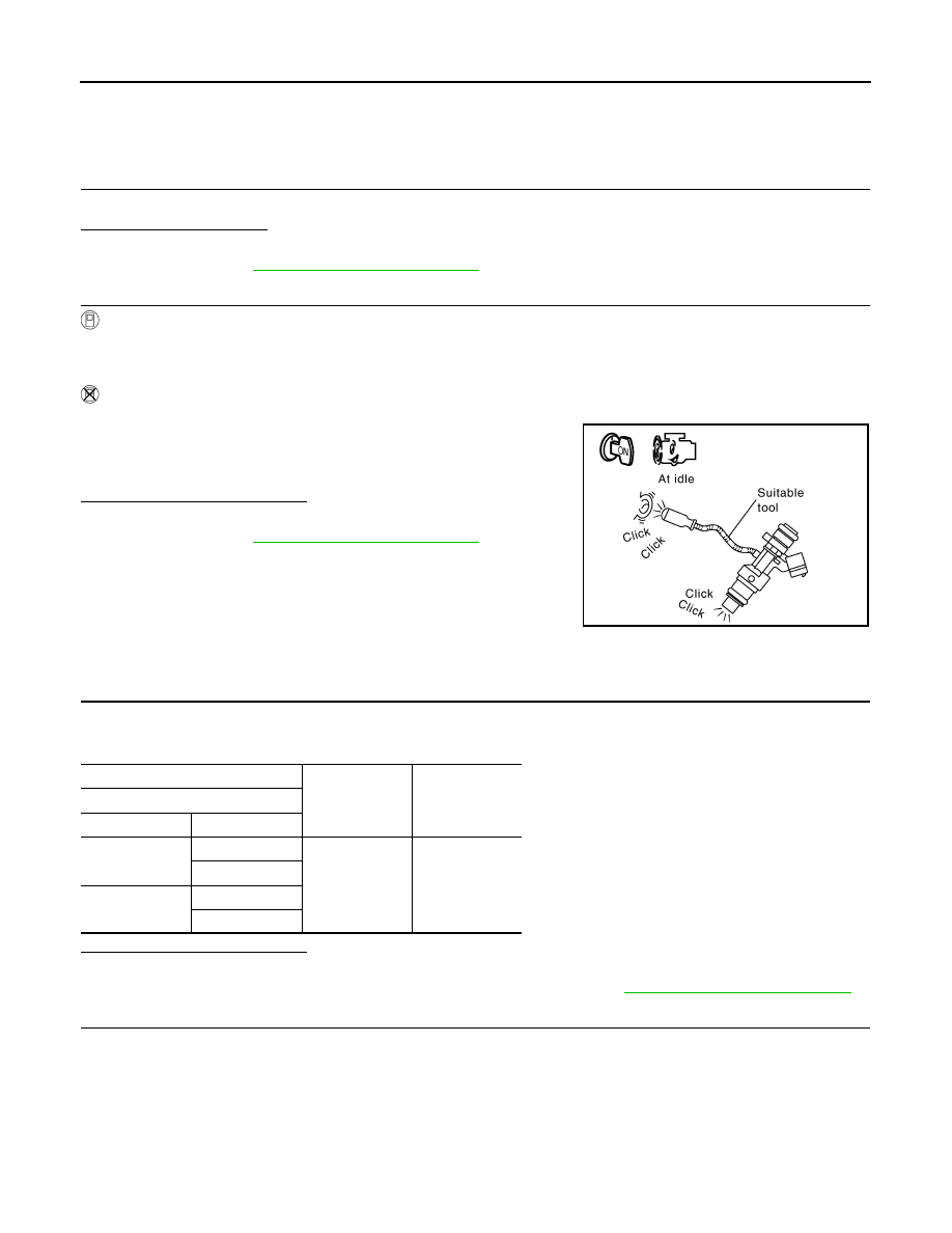
Listen to each fuel injector operating sound.

Is the inspection result normal?

YES

>> INSPECTION END

NO

>> Proceed to 

EC-498, "Diagnosis Procedure"

.

Diagnosis Procedure

INFOID:0000000006218003

1.

CHECK FUEL INJECTOR POWER SUPPLY

1.

Turn ignition switch ON.

2.

Check the voltage between ECM harness connector and ground.

Is the inspection result normal?

YES

>> GO TO 2.

NO

>> Perform the trouble diagnosis for power supply circuit. Refer to 

EC-168, "Diagnosis Procedure"

.

2.

CHECK FUEL INJECTOR CIRCUIT

1.

Turn ignition switch OFF.

2.

Disconnect fuel injector harness connector and ECM harness connector.

3.

Check the continuity between fuel injector harness connector and ECM harness connector.

Clicking sound should be heard.

PBIB3332E

+

Voltage

ECM

Connector

Terminal

F111

46

Ground

Battery voltage

51

E80

111

112

FUEL INJECTOR

EC-499

< DTC/CIRCUIT DIAGNOSIS >

[VK56VD]

C

D

E

F

G

H

I

J

K

L

M

A

EC

N

P

O

4.

Also check harness for short to ground and to power.

Is the inspection result normal?

YES

>> GO TO 3.

NO

>> Repair or replace error-detected parts.

3.

CHECK ECM GROUND CIRCUIT

Check the continuity between ECM harness connector and ground.

Is inspection result normal?

YES

>> GO TO 4.

NO

>> Repair or replace error-detected parts.

4.

CHECK FUEL INJECTOR

Refer to 

EC-499, "Component Inspection"

.

Is the inspection result normal?

YES

>> Check intermittent incident. Refer to 

GI-40, "Intermittent Incident"

.

NO

>> Replace malfunctioning fuel injector. Refer to 

EM-49, "Removal and Installation"

.

Component Inspection

INFOID:0000000006218004

1.

CHECK FUEL INJECTOR

1.

Turn ignition switch OFF.

2.

Disconnect fuel injector harness connector.

3.

Check the resistance between fuel injector terminals as per the following.

Cylinder

+

Continuity

Fuel injector

ECM

Connector

Terminal

Connector

Terminal

1

F123

1

F110

101

Existed

2

108

2

F124

1

F111

7

2

4

3

F125

1

F111

6

2

3

4

F126

1

F110

107

2

104

5

F127

1

F111

2

2

9

6

F128

1

F110

102

2

109

7

F129

1

F110

106

2

103

8

F130

1

F111

1

2

8

+

Continuity

ECM

Connector

Terminal

F111

5

Ground

Exsisted

E80

114

115

EC-500

< DTC/CIRCUIT DIAGNOSIS >

[VK56VD]

FUEL INJECTOR

Is the inspection result normal?

YES

>> INSPECTION END

NO

>> Replace malfunctioning fuel injector. Refer to 

EM-49, "Removal and Installation"

.

Injector

Condition

Resistance

+

Terminal

1

2

Temperature

10 - 60

°

C (50 - 140

°

F)

1.44 - 1.73 

HIGH PRESSURE FUEL PUMP

EC-501

< DTC/CIRCUIT DIAGNOSIS >

[VK56VD]

C

D

E

F

G

H

I

J

K

L

M

A

EC

N

P

O

HIGH PRESSURE FUEL PUMP

Component Function Check

INFOID:0000000006218005

1.

CHECK HIGH PRESSURE FUEL PUMP FUNCTION

 WITH CONSULT-III

1.

Start engine.

2.

Check “FUEL PRES SEN V” in “DATA MONITOR” mode with CONSULT-III.

 WITHOUT CONSULT-III

1.

Start engine.

2.

Check the voltage between ECM harness connector and ground.

Is the inspection result normal?

YES

>> INSPECTION END

NO

>> Proceed to 

EC-501, "Diagnosis Procedure"

.

Diagnosis Procedure

INFOID:0000000006218006

1.

CHECK HIGH PRESSURE FUEL PUMP SOLENOID CIRCUIT

1.

Turn ignition switch OFF.

2.

Disconnect ECM harness connector and high pressure fuel pump harness connector.

3.

Check the continuity between ECM harness connector and high pressure fuel pump harness connector.

Monitor Item

Condition

Values/Status

FUEL PRES SEN V

Engine speed: Idle

980 – 1,200 mV

Engine speed: Revving engine from idle to 4,000 rpm 
quickly

1,100 – 2,900 mV

ECM

Condition

Voltage

+

Connector

Terminal

Connector

Terminal

F110

105

E80

175

[Engine is running]
• Warm-up condition
• Idle speed

NOTE:
The pulse cycle changes depending 
on rpm at idle

BATTERY VOLTAGE

(11 - 14 V)

[Engine is running]
• Warm-up condition
• Engine speed: 2,000 rpm

BATTERY VOLTAGE

(11 - 14 V)

JPBIA3340ZZ

JPBIA3341ZZ

+

Continuity

ECM

High pressure fuel pump

Connector

Terminal

Connector

Terminal

F110

105

F24

1

Existed

110

2


Content   ..  628  629  630  631   ..