Infiniti QX56 (Z62). Manual - part 442


  Index      Infiniti     Infiniti QX56 (Z62) - service repair manual 2011 year


Search            


Content   ..  440  441  442  443   ..


Infiniti QX56 (Z62). Manual - part 442


DLK-234

< REMOVAL AND INSTALLATION >

BACK DOOR

BACK DOOR ASSEMBLY : Adjustment

INFOID:0000000006226088

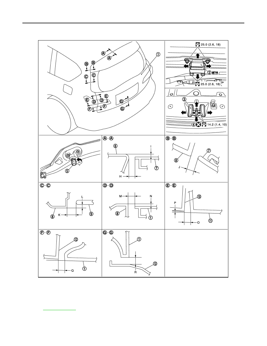
Check the clearance and the surface height between back door and each part by visually and touching.
If the clearance and the surface height are out of specification, adjust them according to the procedures
shown below.

1.

Back door assembly

2.

Back door hinge

3.

Back door striker

4.

TORX bolt

5.

Bumper rubber

6.

Roof

7.

Rear roof spoiler

8.

Body side outer

9.

Back door glass

10. Rear combination lamp

11.

Back up lamp

12. Rear bumper fascia

Refer to 

GI-4, "Components"

 for symbols in the figure.

JMKIA5483GB

BACK DOOR

DLK-235

< REMOVAL AND INSTALLATION >

C

D

E

F

G

H

I

J

L

M

A

B

DLK

N

O

P

Unit: mm (in)

1.

Remove luggage rear plate mask. Refer to 

INT-35, "LUGGAGE REAR PLATE : Removal and Installation"

.

2.

Loosen back door striker mounting bolts.

3.

Loosen back door hinge mounting nuts (back door side).

4.

Loosen bumper rubber (side and lower).

5.

Lift up back door approximately 100 – 150 mm (3.937 – 5.906 in) height then close it lightly and check that
it is engaged firmly with back door closed.

6.

Check the clearance and surface height.

7.

Finally tighten back door hinge, bumper rubber, and back door striker.

8.

Install luggage rear plate mask. Refer to 

INT-35, "LUGGAGE REAR PLATE : Removal and Installation"

.

BACK DOOR STRIKER ADJUSTMENT

Adjust back door striker so that i becomes parallel with back door lock insertion direction.

BACK DOOR STRIKER

BACK DOOR STRIKER : Removal and Installation

INFOID:0000000006226089

REMOVAL

1.

Remove luggage rear plate. Refer to 

INT-35, "LUGGAGE REAR PLATE : Removal and Installation"

.

2.

Remove mounting TORX bolts, and then remove back door striker.

INSTALLATION

Note the following items, and then install in the reverse order of removal.

CAUTION:

• Check back door open/close operation after installation.
• When removing and installing back door striker, check to perform the fitting adjustment. Refer to

DLK-234, "BACK DOOR ASSEMBLY : Adjustment"

.

Portion

Standard

Difference

(LH/RH, MAX)

Roof – Rear roof spoiler

A – A

H

Clearance

5.0 – 9.0

(0.197 – 0.354)

I

Surface height

(

1.0) – (+3.0)

[(

0.039) – (+0.118)]

Body side outer panel – 
Rear roof spoiler

B – B

J

Clearance

3.8 – 7.8

(0.150 – 0.307)

2.0

(0.079)

Body side outer panel – 
Back door glass

C – C

K

Clearance

3.0 – 7.0

(0.118 – 0.276)

2.0

(0.079)

L

Surface height

0.0 – 4.0

(0.000 – 0.157)

2.0

(0.079)

Body side outer panel – 
Back door

D – D

M

Clearance

4.0 – 6.0

(0.157 – 0.236)

1.0

(0.039)

N

Surface height

(

1.0) – (+1.0)

[(

0.039) – (+0.039)]

1.0

(0.039)

Rear combination lamp 
– Back up lamp

E – E

O

Clearance

2.5 – 7.5

(0.098 – 0.295)

2.2

(0.087)

P

Surface height

(

2.2) – (+2.2)

[(

0.087) – (+0.087)]

2.2

(0.087)

Rear bumper fascia – 
Back door

F – F

Q

Clearance

2.9 – 7.1

(0.114 – 0.280)

2.1

(0.083)

Rear bumper fascia – 
Back door

G – G

R

Clearance

4.0 – 8.0

(0.157 – 0.315)

DLK-236

< REMOVAL AND INSTALLATION >

BACK DOOR

BACK DOOR HINGE

BACK DOOR HINGE : Removal and Installation

INFOID:0000000006226090

CAUTION:

• Operate with two workers, because of its heavy weight.
• Use protective tape or cloth to protect from damage during remove and installation.

REMOVAL

1.

Remove back door assembly. Refer to 

DLK-232, "BACK DOOR ASSEMBLY : Removal and Installation"

2.

Remove back door hinge mounting nuts (body side), and then remove back door hinge.

INSTALLATION

Note the following items, and then install in the reverse order of removal.

CAUTION:

• Apply anticorrosive agent onto the mounting surface.
• Check back door open/close operation after installation.
• Check back door hinge rotating part for poor lubrication. If necessary, apply body grease.
• When removing and installing back door assembly, perform the fitting adjustment. Refer to 

DLK-234,

"BACK DOOR ASSEMBLY : Adjustment"

.

• After installation, apply touch-up paint (the body color) onto the head of back door hinge mounting

nuts.

BACK DOOR STAY

BACK DOOR STAY : Removal and Installation

INFOID:0000000006226091

REMOVAL

1.

Support back door lock with the proper material to prevent it from falling.

WARNING:

Body injury may occur if no supporting rod is holding the back door open when removing the
back door stay.

2.

Remove the metal clip (3) located on the connection between
the back door stay (1) and the stud ball (2) (back door side) by
using a flatted-blade screwdriver (A).

3.

Remove back door stay (back door side).

4.

In the same way, remove back door stay (body side).

INSTALLATION

Note the following item, and then install in the reverse order of removal.

CAUTION:

Check back door open/close operation after installation.

JMKIA2255ZZ

BACK DOOR

DLK-237

< REMOVAL AND INSTALLATION >

C

D

E

F

G

H

I

J

L

M

A

B

DLK

N

O

P

BACK DOOR STAY : Disposal 

INFOID:0000000006226092

1.

Fix back door stay (1) using a vise (C).

2.

Using hacksaw (A) slowly make 2 holes in the back door stay, in
numerical order as shown in the figure.

CAUTION:

• When cutting a hole on back door stay, always cover a

hacksaw using a shop cloth (B) to avoid scattering metal
fragments or oil. 

• Wear eye protection (safety glasses).
• Wear gloves.

BACK DOOR WEATHER-STRIP

BACK DOOR WEATHER-STRIP : Removal and Installation

INFOID:0000000006226093

REMOVAL

1.

Remove stud ball of back door support rod from back door assembly. Refer to 

DLK-247, "BACK DOOR

SUPPORT ROD : Removal and Installation"

.

2.

Pull up and remove engagement with body from weather-strip joint.

CAUTION:

Never pull strongly on weather-strip.

INSTALLATION

1.

Working from the upper section, align weather-strip mark with vehicle center position mark and install
weather-strip onto the vehicle.

2.

For the lower section, align weather-strip seam with center of back door striker.

3.

Pull weather-strip gently to ensure that there is no loose section.
NOTE:
Check that weather-strip is fit tightly at each corner and luggage rear plate.

4.

Install mounting bolts of power back door drive assembly (Back door side).

5.

Install stud ball of back door support rod to back door assembly. Refer to 

DLK-247, "BACK DOOR SUP-

PORT ROD : Removal and Installation"

.

JMKIA3336ZZ

A:

20 mm (0.787 in)

B:

Cut at the groove.

JMKIA3609ZZ


Content   ..  440  441  442  443   ..