Infiniti QX56 (Z62). Manual - part 439
DLK-222
< REMOVAL AND INSTALLATION >
FRONT FENDER
FRONT FENDER
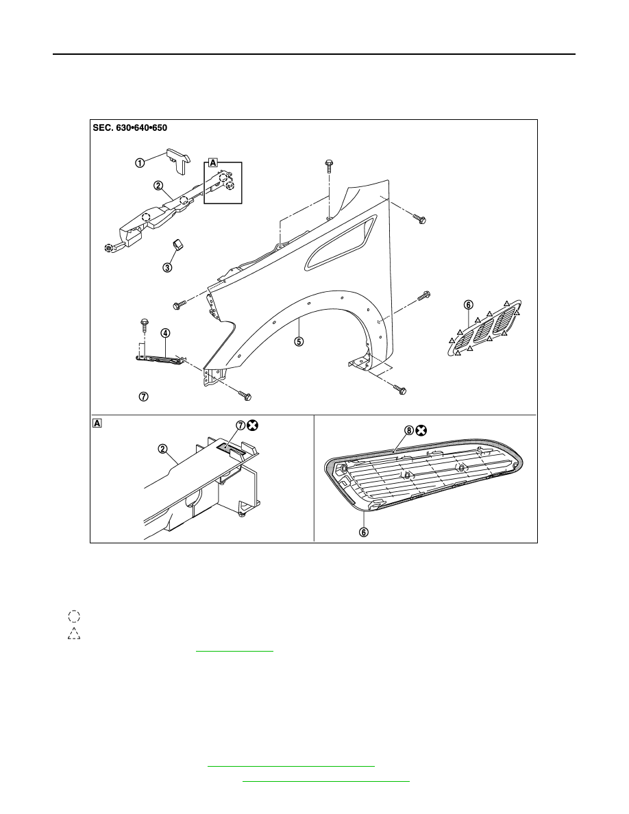
Exploded View
INFOID:0000000006226070
FRONT FENDER
FRONT FENDER : Removal and Installation
INFOID:0000000006226071
CAUTION:
Use a shop cloth to protect the body from being damaged during removal and installation.
REMOVAL
1.
Remove side step. Refer to
EXT-45, "Removal and Installation"
2.
Remove front over fender. Refer to
EXT-26, "Removal and Installation"
.
1.
Cowl top seal
2.
Front fender drip cover
3.
Hood side bumper
4.
Front fender stay
5.
Front fender assembly
6.
Front fender duct
7.
Double-sided tape
[t: 0.8 mm (0.031 in)]
8.
Double-sided tape
[t: 1.2 mm (0.047 in)]
: Clip
: Pawl
Refer to for symbols in the figure.
JMKIA5481ZZ