Infiniti QX56 (Z62). Manual - part 140


  Index      Infiniti     Infiniti QX56 (Z62) - service repair manual 2011 year


Search            


Content   ..  138  139  140  141   ..


Infiniti QX56 (Z62). Manual - part 140


ABS ACTUATOR AND ELECTRIC UNIT (CONTROL UNIT)

BRC-45

< ECU DIAGNOSIS INFORMATION >

[WITH VDC]

C

D

E

G

H

I

J

K

L

M

A

B

BRC

N

O

P

ECU DIAGNOSIS INFORMATION

ABS ACTUATOR AND ELECTRIC UNIT (CONTROL UNIT)

Reference Value

INFOID:0000000006222579

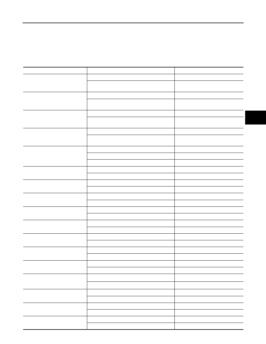
CONSULT-III DATA MONITOR STANDARD VALUE

Monitor item

Condition

Reference values in normal operation

FR LH SENSOR

Vehicle stopped

0.00 km/h (MPH)

When driving

(Note 1)

Nearly matches the speedometer dis-
play (within 

±

10%)

FR RH SENSOR

Vehicle stopped

0.00 km/h (MPH)

When driving

(Note 1)

Nearly matches the speedometer dis-
play (within 

±

10%)

RR LH SENSOR

Vehicle stopped

0.00 km/h (MPH)

When driving

(Note 1)

Nearly matches the speedometer dis-
play (within 

±

10%)

RR RH SENSOR

Vehicle stopped

0.00 km/h (MPH)

When driving

(Note 1)

Nearly matches the speedometer dis-
play (within 

±

10%)

DECEL G-SEN

When stopped

Approx. 0 G

During acceleration

Positive value

During deceleration

Negative value

FR RH IN SOL

Active

On

Inactive

Off

FR RH OUT SOL

Active

On

Inactive

Off

FR LH IN SOL

Active

On

Inactive

Off

FR LH OUT SOL

Active

On

Inactive

Off

RR RH IN SOL

Active

On

Inactive

Off

RR RH OUT SOL

Active

On

Inactive

Off

RR LH IN SOL

Active

On

Inactive

Off

RR LH OUT SOL

Active

On

Inactive

Off

EBD WARN LAMP

When brake warning lamp is ON

(Note 2)

On

When brake warning lamp is OFF

(Note 2)

Off

STOP LAMP SW

Brake pedal depressed

On

Brake pedal not depressed

Off

MOTOR RELAY

Active

On

Inactive

Off

ACTUATOR RLY

Active

On

Inactive (in fail-safe mode)

Off

BRC-46

< ECU DIAGNOSIS INFORMATION >

[WITH VDC]

ABS ACTUATOR AND ELECTRIC UNIT (CONTROL UNIT)

ABS WARN LAMP

When ABS warning lamp is ON

(Note 2)

On

When ABS warning lamp is OFF

(Note 2)

Off

OFF LAMP

When VDC OFF indicator lamp is ON

(Note 2)

On

When VDC OFF indicator lamp is OFF

(Note 2)

Off

OFF SW

VDC OFF switch ON

On

VDC OFF switch OFF

Off

SLIP/VDC LAMP

When VDC warning lamp is ON or Blinking

(Note 2)

On

When VDC warning lamp is OFF

(Note 2)

Off

BATTERY VOLT

Ignition switch ON

10 – 16 V

GEAR

Driving

1 – 7
Depending on shift status

ENGINE SPEED

Engine stopped

0 tr/min

Engine running

Almost same reading as tachometer

YAW RATE SEN

Vehicle stopped

Approx. 0 d/s

Turning right

Negative value

Turning left

Positive value

R POSI SIG

When selector lever is in the R position

On

When selector lever is in the other position than R

Off

4WD MODE MON

(Note 3)

When 4WD sift switch is AUTO position

AUTO

When 4WD sift switch is 4H position

LOCK

When 4WD sift switch is 4L position

##

N POSI SIG

When selector lever is in the N position

On

When selector lever is in the other position than N

Off

CV1

Active

On

Inactive

Off

CV2

Active

On

Inactive

Off

SV1

Active

On

Inactive

Off

SV2

Active

On

Inactive

Off

STOP LAMP SW2

Brake pedal depressed

On

Brake pedal not depressed

Off

ACCEL POS SIG

Never depress accelerator pedal
(with ignition switch ON)

0%

Depress accelerator pedal
(with ignition switch ON)

0 – 100%

SIDE G-SENSOR

Vehicle stopped

Approx. 0 m/s

2

Right turn

Negative value

Left turn

Positive value

STR ANGLE SIG

When driving straight

0

±

2.5

°

When steering wheel is steered to LH by 90

°

Approx. +90

°

When steering wheel is steered to RH by 90

°

Approx. –90

°

Monitor item

Condition

Reference values in normal operation

ABS ACTUATOR AND ELECTRIC UNIT (CONTROL UNIT)

BRC-47

< ECU DIAGNOSIS INFORMATION >

[WITH VDC]

C

D

E

G

H

I

J

K

L

M

A

B

BRC

N

O

P

Note 1: Confirm tire pressure is standard value.
Note 2: Refer to 

BRC-16, "System Description"

 for ON/Blinking/OFF conditions of each warning lamp and indi-

cator lamp.
Note 3: Models with 4WD System
Note 4: Models with Advanced Driver Assistance System
Note 5: USS means “hill start assist”.

Fail-safe

INFOID:0000000006222580

VDC FUNCTION, TCS FUNCTION, hill start assist FUNCTION AND BRAKE LIMITED SLIP DIFFER-
ENTIAL (BLSD) FUNCTION

VDC warning lamp in combination meter turn ON when a malfunction occurs in system [ABS actuator and
electric unit (control unit)]. The control is suspended for VDC function, TCS function, hill start assist function
and brake limited slip differential (BLSD) function. The Vehicle status becomes the same as models without

PRESS SENSOR

Brake pedal not depressed

Approx. 0 bar

Brake pedal depressed

(

40) – (+300) bar

ACCUM PRESS SEN

With ignition switch ON 

Approx. 0 – 210 bar (Proportional to the 
amount of accumulated pressure in the 
accumulator)

CONT PRESS SEN

(Note 4)

Brake pedal not depressed

Approx. 0 bar

Brake pedal depressed

(

40) – (+300) bar

EBD SIGNAL

EBD is active

On

EBD is inactive

Off

ABS SIGNAL

ABS is active

On

ABS is inactive

Off

TCS SIGNAL

TCS is active

On

TCS is inactive

Off

VDC SIGNAL

VDC is active

On

VDC is inactive

Off

EBD FAIL SIG

In EBD fail-safe

On

EBD is normal

Off

ABS FAIL SIG

In ABS fail-safe

On

ABS is normal

Off

TCS FAIL SIG

In TCS fail-safe

On

TCS is normal

Off

VDC FAIL SIG

In VDC fail-safe

On

VDC is normal

Off

CRANKING SIG

At cranking

On

Other than at cranking

Off

FLUID LEV SW

When brake fluid level switch is ON (brake fluid level 
is less than the specified level)

On

When brake fluid level switch is OFF

Off

PARK BRAKE SW

When parking brake is active

On

Parking brake is released

Off

STP ON RLY

Stop lamp relay is active

On

Stop lamp relay is inactive

Off

USS SIG

(Note 5)

hill start assist is active

On

hill start assist is inactive

Off

Monitor item

Condition

Reference values in normal operation

BRC-48

< ECU DIAGNOSIS INFORMATION >

[WITH VDC]

ABS ACTUATOR AND ELECTRIC UNIT (CONTROL UNIT)

VDC function, TCS function, hill start assist function and brake limited slip differential (BLSD) function. How-
ever, ABS function and EBD function are operated normally.

ABS FUNCTION

ABS warning lamp and VDC warning lamp in combination meter turn ON when a malfunction occurs in system
[ABS actuator and electric unit (control unit)]. The control is suspended for VDC function, TCS function, ABS
function, hill start assist function and brake limited slip differential (BLSD) function. The vehicle status
becomes the same as models without VDC function, TCS function, ABS function, hill start assist function and
brake limited slip differential (BLSD) function. However, EBD function is operated normally.
NOTE:
ABS self-diagnosis sound may be heard the same as in the normal condition, because self-diagnosis is per-
formed when ignition switch turns ON and when vehicle initially starts.

EBD FUNCTION

ABS warning lamp, brake warning lamp and VDC warning lamp in combination meter turn ON when a mal-
function occurs in system [ABS actuator and electric unit (control unit)]. The control is suspended for VDC
function, TCS function, ABS function, EBD function, hill start assist function and brake limited slip differential
(BLSD) function. The vehicle status becomes the same as models without VDC function, TCS function, ABS
function, EBD function, hill start assist function and brake limited slip differential (BLSD) function.

DTC

Malfunction detected condition

Fail-safe condition

C1101

When an open circuit is detected in rear RH wheel sensor circuit.

The following functions are sus-
pended.
• VDC function
• TCS function
• ABS function
• EBD function (only when both 2 

rear wheels are malfunctioning)

• hill start assist function
• Brake limited slip differential 

(BLSD) function

C1102

When an open circuit is detected in rear LH wheel sensor circuit.

C1103

When an open circuit is detected in front RH wheel sensor circuit.

C1104

When an open circuit is detected in front LH wheel sensor circuit.

C1105

• When power supply voltage of rear RH wheel sensor is low.
• When distance between rear RH wheel sensor and rear RH wheel sensor rotor is 

large.

• When installation of rear RH wheel sensor or rear RH wheel sensor rotor is not 

normal.

C1106

• When power supply voltage of rear LH wheel sensor is low.
• When distance between rear LH wheel sensor and rear LH wheel sensor rotor is 

large.

• When installation of rear LH wheel sensor or rear LH wheel sensor rotor is not nor-

mal.

C1107

• When power supply voltage of front RH wheel sensor is low.
• When distance between front RH wheel sensor and front RH wheel sensor rotor 

is large.

• When installation of front RH wheel sensor or front RH wheel sensor rotor is not 

normal.

C1108

• When power supply voltage of front LH wheel sensor is low.
• When distance between front LH wheel sensor and front LH wheel sensor rotor is 

large.

• When installation of front LH wheel sensor or front LH wheel sensor rotor is not 

normal.

C1109

• When ignition voltage is 10 V or less.
• When ignition voltage is 16 V or more.

The following functions are sus-
pended.
• VDC function
• TCS function
• ABS function
• EBD function
• hill start assist function
• Brake limited slip differential 

(BLSD) function

C1111

• When a malfunction is detected in motor or motor relay.
• When a low pressure malfunction is detected in accumulator.
• When a malfunction is detected in accumulator pressure sensor.


Content   ..  138  139  140  141   ..