Infiniti QX56 (Z62). Manual - part 139
DIAGNOSIS SYSTEM [ABS ACTUATOR AND ELECTRIC UNIT (CONTROL
UNIT)]
BRC-41
< SYSTEM DESCRIPTION >
[WITH VDC]
C
D
E
G
H
I
J
K
L
M
A
B
BRC
N
O
P
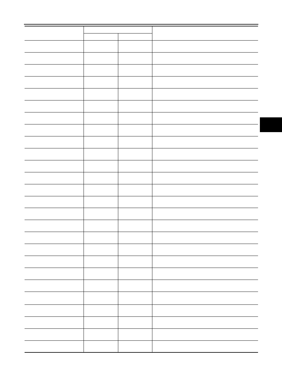
FR RH IN SOL
(On/Off)
×
Operation status of front RH wheel ABS IN valve is dis-
played.
FR RH OUT SOL
(On/Off)
×
Operation status of front RH wheel ABS OUT valve is dis-
played.
FR LH IN SOL
(On/Off)
×
Operation status of front LH wheel ABS IN valve is dis-
played.
FR LH OUT SOL
(On/Off)
×
Operation status of front LH wheel ABS OUT valve is dis-
played.
RR RH IN SOL
(On/Off)
×
Operation status of rear RH wheel ABS IN valve is displayed
RR RH OUT SOL
(On/Off)
×
Operation status of rear RH wheel ABS OUT valve is dis-
played.
RR LH IN SOL
(On/Off)
×
Operation status of rear LH wheel ABS IN valve is dis-
played.
RR LH OUT SOL
(On/Off)
×
Operation status of rear LH wheel ABS OUT valve is dis-
played.
EBD WARN LAMP
(On/Off)
Brake warning lamp ON/OFF status is displayed.
(Note 1)
STOP LAMP SW
(On/Off)
×
×
Stop lamp switch signal input status is displayed.
MOTOR RELAY
(On/Off)
×
ABS motor and motor relay status is displayed.
ACTUATOR RLY
(On/Off)
×
ABS actuator relay status is displayed.
ABS WARN LAMP
(On/Off)
×
ABS warning lamp ON/OFF status is displayed.
(Note 1)
OFF LAMP
(On/Off)
×
VDC OFF indicator lamp ON/OFF status is displayed.
(Note 1)
OFF SW
(On/Off)
×
×
VDC OFF switch signal input status is displayed.
SLIP/VDC LAMP
(On/Off)
×
VDC warning lamp ON/OFF status is displayed.
(Note 1)
BATTERY VOLT
(V)
×
×
Voltage supplied to ABS actuator and electric unit (control
unit) is displayed.
GEAR
×
×
Current gear position judged from current gear position sig-
nal is displayed.
ENGINE SPEED
(tr/min)
×
×
Engine speed status is displayed.
YAW RATE SEN
(d/s)
×
×
Yaw rate detected by yaw rate sensor is displayed.
R POSI SIG
(On/Off)
R range signal input status judged from R range signal is
displayed.
4WD MODE MON
(Note 2)
(AUTO/LOCK/##)
×
×
4WD control status is displayed.
N POSI SIG
(On/Off)
N range signal input status judged from N range signal is
displayed.
CV1
(On/Off)
Cut valve 1 operation status is displayed.
CV2
(On/Off)
Cut valve 2 operation status is displayed.
SV1
(On/Off)
Suction valve 1 operation status is displayed.
Item (Unit)
Monitor item selection
Note
INPUT SIGNALS
MAIN ITEMS