Content .. 1345 1346 1347 1348 ..
Infiniti QX56 (Z62). Manual - part 1347
SERVICE DATA AND SPECIFICATIONS (SDS)
TM-297
< SERVICE DATA AND SPECIFICATIONS (SDS)
[7AT: RE7R01B]
C
E
F
G
H
I
J
K
L
M
A
B
TM
N
O
P
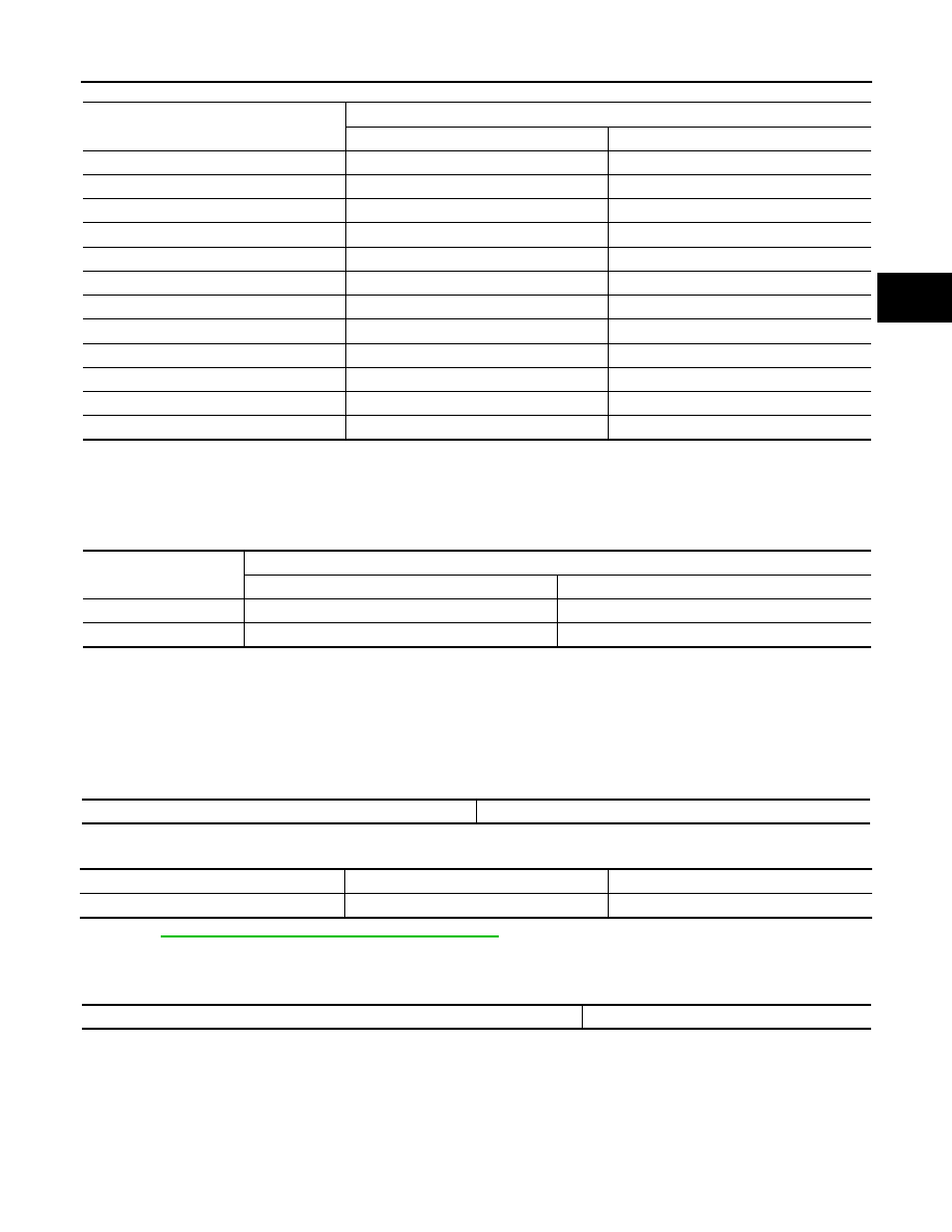
Unit: km/h (MPH)
• At half throttle, the accelerator opening is 4/8 of the full opening.
• The vehicle speed included in the above table is a speed with the tow mode ON and a heavy load towed.
Vehicle Speed at Which Lock-up Occurs/Releases
INFOID:0000000006226946
• Vehicle speed with D
5
position.
• At closed throttle, the accelerator opening is less than 1/8 condition. (Closed throttle position signal OFF)
• At half throttle, the accelerator opening is 4/8 of the full opening.
Stall Speed
INFOID:0000000006226947
2WD MODELS
4WD MODELS
DLN-18, "4WD SYSTEM : System Description"
.
Torque Converter
INFOID:0000000006226948
Gear position
Throttle position
Full throttle
Half throttle
D
1
→
D
2
57 – 61 (35 – 38)
50 – 54 (31 – 34)
D
2
→
D
3
89 – 97 (55 – 60)
76 – 84 (47 – 52)
D
3
→
D
4
141 – 151 (88 – 94)
116 – 126 (72 – 78)
D
4
→
D
5
205 – 215 (127 – 134)
159 – 169 (99 – 105)
D
5
→
D
6
251 – 261 (156 – 162)
189 – 199 (117 – 124)
D
6
→
D
7
251 – 261 (156 – 162)
215 – 225 (134 – 140)
D
7
→
D
6
240 – 250 (149 – 155)
161 – 171 (100 – 106)
D
6
→
D
5
240 – 250 (149 – 155)
130 – 140 (81 – 87)
D
5
→
D
4
180 – 190 (112 – 118)
84 – 94 (52 – 58)
D
4
→
D
3
126 – 136 (78 – 85)
58 – 68 (36 – 42)
D
3
→
D
2
66 – 74 (41 – 46)
30 – 38 (19 – 24)
D
2
→
D
1
24 – 28 (15 – 17)
10 – 14 (6 – 9)
Throttle position
Vehicle speed
km/h (MPH)
Lock-up ON
Lock-up OFF
Closed throttle
50 – 58 (31 – 36)
50 – 58 (31 – 36)
Half throttle
163 – 171 (101 – 106)
163 – 171 (101 – 106)
Stall speed
1,777 – 2,077 rpm
4WD shift switch*
AUTO, 4H
4L
Stall speed
1,777 – 2,077 rpm
1,540 – 1,840 rpm
Dimension between end of converter housing and torque converter
24.0 mm (0.94 in)