Infiniti QX56 (Z62). Manual - part 132
COMPONENT PARTS
BRC-13
< SYSTEM DESCRIPTION >
[WITH VDC]
C
D
E
G
H
I
J
K
L
M
A
B
BRC
N
O
P
Component Description
INFOID:0000000006222560
*1: Models with Advanced Driver Assistance System
*2: Models with 4WD system
D.
ABS warning lamp, brake warning
lamp, VDC warning lamp, VDC OFF
indicator lamp
E.
Back of spiral cable assembly
F.
Center console assembly
G.
Under center console assembly
H.
Rear wheel hub and bearing assem-
bly
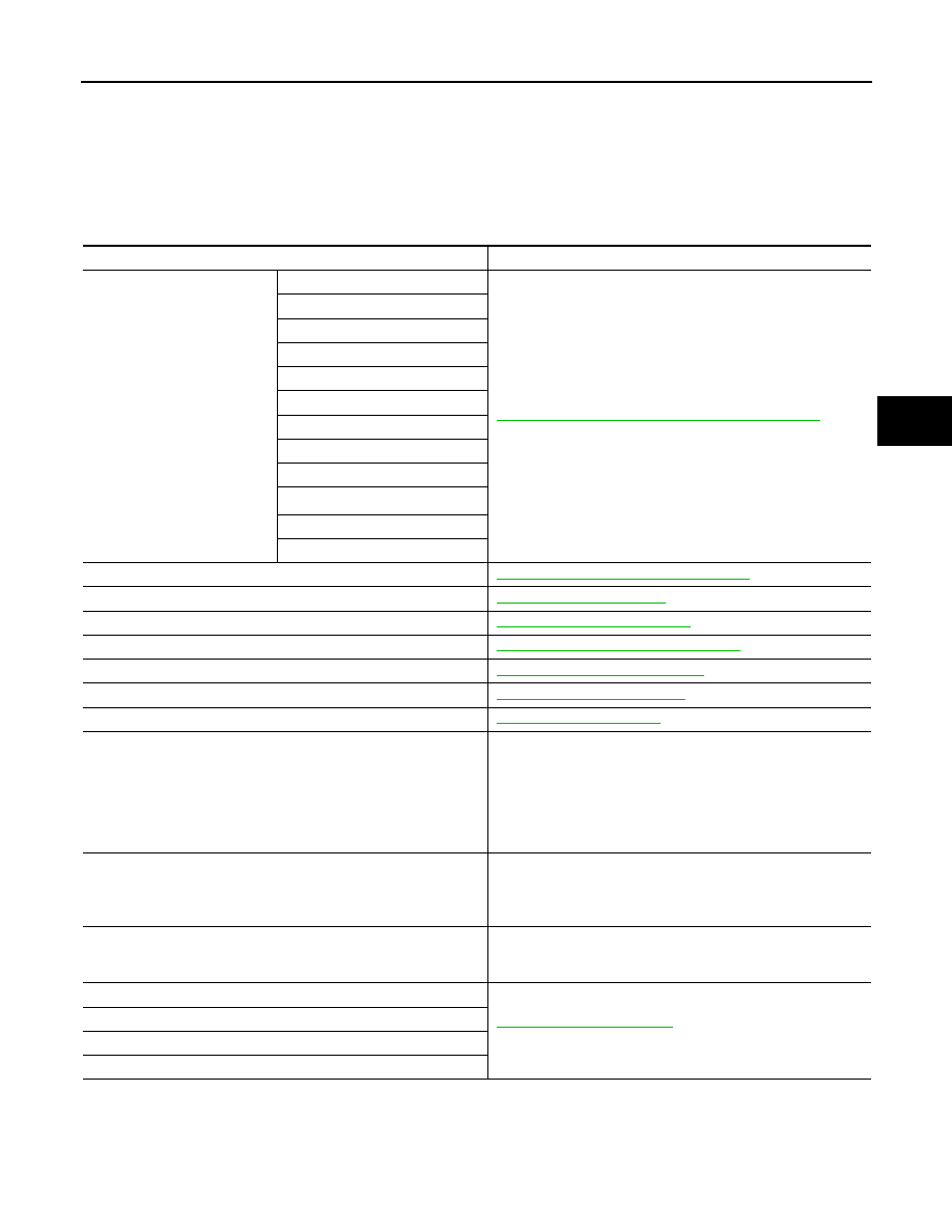
Component
Reference/Function
ABS actuator and electric unit
(control unit)
Motor/accumulator assembly
BRC-14, "ABS Actuator and Electric Unit (Control Unit)"
Motor relay
Actuator relay (main relay)
ABS IN valve
ABS OUT valve
Cut valve 1
Cut valve 2
Suction valve 1
Suction valve 2
Control pressure sensor
*1
Accumulator pressure sensor
Master cylinder pressure sensor
Wheel sensor
BRC-14, "Wheel Sensor and Sensor Rotor"
Stop lamp switch
Steering angle sensor
BRC-15, "Steering Angle Sensor"
Yaw rate/side/decel G sensor
BRC-15, "Yaw Rate/Side/Decel G sensor"
Brake fluid level switch
BRC-15, "Brake Fluid Level Switch"
Parking brake switch
BRC-15, "Parking Brake Switch"
VDC OFF switch
ECM
Mainly transmits the following signals to ABS actuator and elec-
tric unit (control unit) via CAN communication.
• Accelerator pedal position signal
• Engine speed signal
Mainly receives the following signals from ABS actuator and
electric unit (control unit) via CAN communication.
• Target throttle position signal
TCM
Mainly transmits the following signals to ABS actuator and elec-
tric unit (control unit) via CAN communication.
• Shift position signal
• Current gear position signal
Transfer control unit
*2
Mainly transmits the following signals to ABS actuator and elec-
tric unit (control unit) via CAN communication.
• Current 4WD mode signal
ABS warning lamp
Brake warning lamp
VDC warning lamp
VDC OFF indicator lamp