Content .. 1285 1286 1287 1288 ..
Infiniti QX56 (Z62). Manual - part 1287
SYSTEM
TM-57
< SYSTEM DESCRIPTION >
[7AT: RE7R01B]
C
E
F
G
H
I
J
K
L
M
A
B
TM
N
O
P
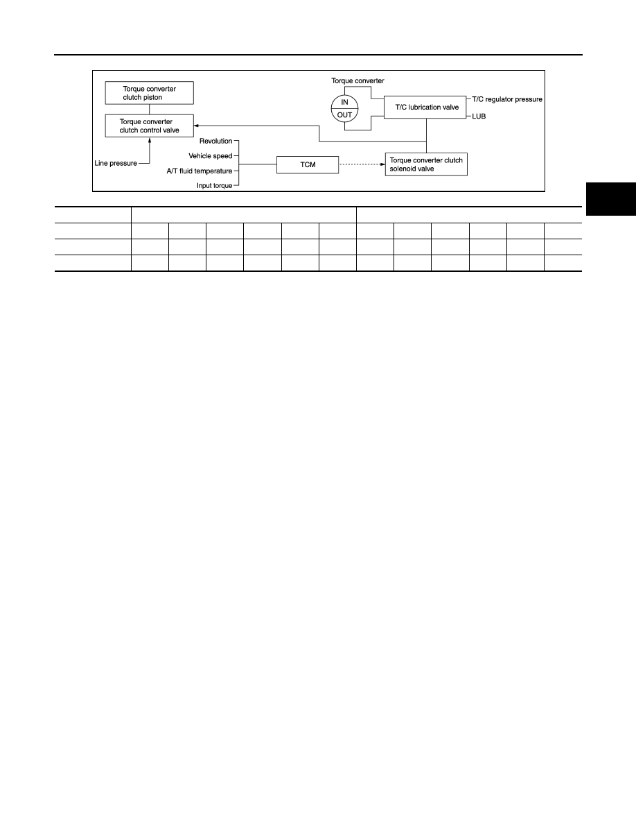
Lock-up Operation Condition Table
Lock-up released
• In the lock-up released state, the torque converter clutch control valve is set into the unlocked state by the
torque converter clutch solenoid and the lock-up apply pressure is drained.
in this way, the torque converter clutch piston is not coupled.
Lock-up Applied
• In the lock-up applied state, the torque converter clutch control valve is set into the locked state by the
torque converter clutch solenoid and lock-up apply pressure is generated.
In this way, the torque converter clutch piston is pressed and coupled.
Smooth Lock-up Control
When shifting from the lock-up released state to the lock-up applied state, the current output to the torque con-
verter clutch solenoid is controlled with the TCM. In this way, when shifting to the lock-up applied state, the
torque converter clutch is temporarily set to the half-clutched state to reduce the shock.
Half-clutched State
• The current output from the TCM to the torque converter clutch solenoid is varied to steadily increase the
torque converter clutch solenoid pressure.
In this way, the lock-up apply pressure gradually rises and while the torque converter clutch piston is put into
half-clutched states, the torque converter clutch piston operating pressure is increased and the coupling is
completed smoothly.
Slip Lock-up Control
• In the slip region, the torque converter clutch solenoid current is controlled with the TCM to put it into the
half-clutched state. This absorbs the engine torque fluctuation and lock-up operates from low speed.
This raises the fuel efficiency for 2GR, 3GR, 4GR, 5GR, 6GR and 7GR.
A/T SHIFT LOCK SYSTEM
JSDIA0847GB
Selector lever
“D” position
“M” position
Gear position
7
6
5
4
3
2
7
6
5
4
3
2
Lock-up
×
–
–
–
–
–
×
×
×
×
×
×
Slip lock-up
×
×
×
×
×
×
×
×
×
×
×
×