Content .. 1176 1177 1178 1179 ..
Infiniti QX56 (Z62). Manual - part 1178
SEC-102
< DTC/CIRCUIT DIAGNOSIS >
[WITH INTELLIGENT KEY SYSTEM]
B2612 STEERING STATUS
B2612 STEERING STATUS
DTC Logic
INFOID:0000000006226256
DTC DETECTION LOGIC
NOTE:
• If DTC B2612 is displayed with DTC U1000, first perform the trouble diagnosis for DTC U1000. Refer to
.
• If DTC B2612 is displayed with DTC U1010, first perform the trouble diagnosis for DTC U1010. Refer to
.
DTC CONFIRMATION PROCEDURE
1.
PERFORM DTC CONFIRMATION PROCEDURE 1
1.
Press push-button ignition switch under the following conditions and wait 1 second or more.
-
Selector lever: In the P position
-
Brake pedal: Not depressed
2.
Check DTC in “Self Diagnostic Result” mode of “BCM” using CONSULT-III.
Is DTC detected?
YES
>> Go to
SEC-102, "Diagnosis Procedure"
.
NO
>> GO TO 2.
2.
PERFORM DTC CONFIRMATION PROCEDURE 2
1.
Turn ignition switch ON.
2.
Turn ignition switch OFF.
3.
Press driver side door switch and wait 1 second or more.
4.
Check DTC in “Self Diagnostic Result” mode of “BCM” using CONSULT-III.
Is DTC detected?
YES
>> Go to
SEC-102, "Diagnosis Procedure"
.
NO
>> INSPECTION END
Diagnosis Procedure
INFOID:0000000006226257
1.
CHECK IPDM E/R INPUT SIGNAL
1.
Turn ignition switch OFF.
2.
Check voltage between IPDM E/R harness connector and ground.
NOTE:
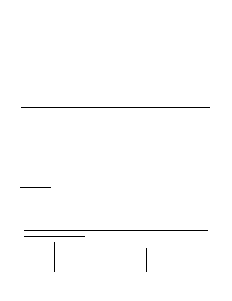
DTC No.
Trouble diagnosis name
DTC detecting condition
Possible causes
B2612
S/L STATUS
The following 2 state signals are different.
• Steering lock state recognition of BCM
• Steering lock state signal from IPDM E/R
• Harness or connectors
(CAN communication line is open or shorted.)
• Harness or connectors
(Steering lock unit circuit is open or shorted.)
• Steering lock unit
• IPDM E/R
• BCM
(+)
(–)
Condition
Voltage (V)
(Approx.)
IPDM E/R
Connector
Terminal
E17
63
Ground
Steering lock unit
Lock
12
Unlock
0
65
Lock
0
Unlock
12