Content .. 1106 1107 1108 1109 ..
Infiniti QX56 (Z62). Manual - part 1108
C1801 VHCL HEIGHT SENSOR
SCS-69
< DTC/CIRCUIT DIAGNOSIS >
[AIR LEVELIZER CONTROL SYSTEM]
C
D
F
G
H
I
J
K
L
M
A
B
SCS
N
O
P
DTC/CIRCUIT DIAGNOSIS
C1801 VHCL HEIGHT SENSOR
DTC Logic
INFOID:0000000006256062
DTC DETECTION LOGIC
DTC CONFIRMATION PROCEDURE
1.
PRECONDITIONING
If “DTC CONFIRMATION PROCEDURE” has been previously conducted, always turn ignition switch OFF
andwait at least 10 seconds before conducting the next test.
>> GO TO 2.
2.
CHECK DTC DETECTION
With CONSULT-III
1.
Turn ignition switch ON and wait 60 seconds or more.
2.
Perform “Self Diagnostic Results” in “E-SUS”.
Is “C1801” detected ?
YES
>> Go to
.
NO
>> INSPECTION END
Diagnosis Procedure
INFOID:0000000006256063
1.
CHECK APPEARANCE
Visually check for malfunction of suspension components, installing malfunction, or deformation of vehicle
height sensor.
Is the inspection result normal?
YES
>> GO TO 2.
NO
>> Repaire or replace damaged parts.
2.
CHECK POWER SUPPLY CIRCUIT (PART 1)
1.
Disconnect vehicle height sensor connector.
2.
Turn ignition switch ON.
CAUTION:
Never start the engine.
3.
Check voltage between vehicle height sensor harness connector and ground.
Is the inspection result normal?
YES
>> GO TO 4.
NO
>> GO TO 3.
3.
CHECK POWER SUPPLY CIRCUIT (PART 2)
1.
Turn ignition switch OFF.
2.
Disconnect air levelizer control module connector.
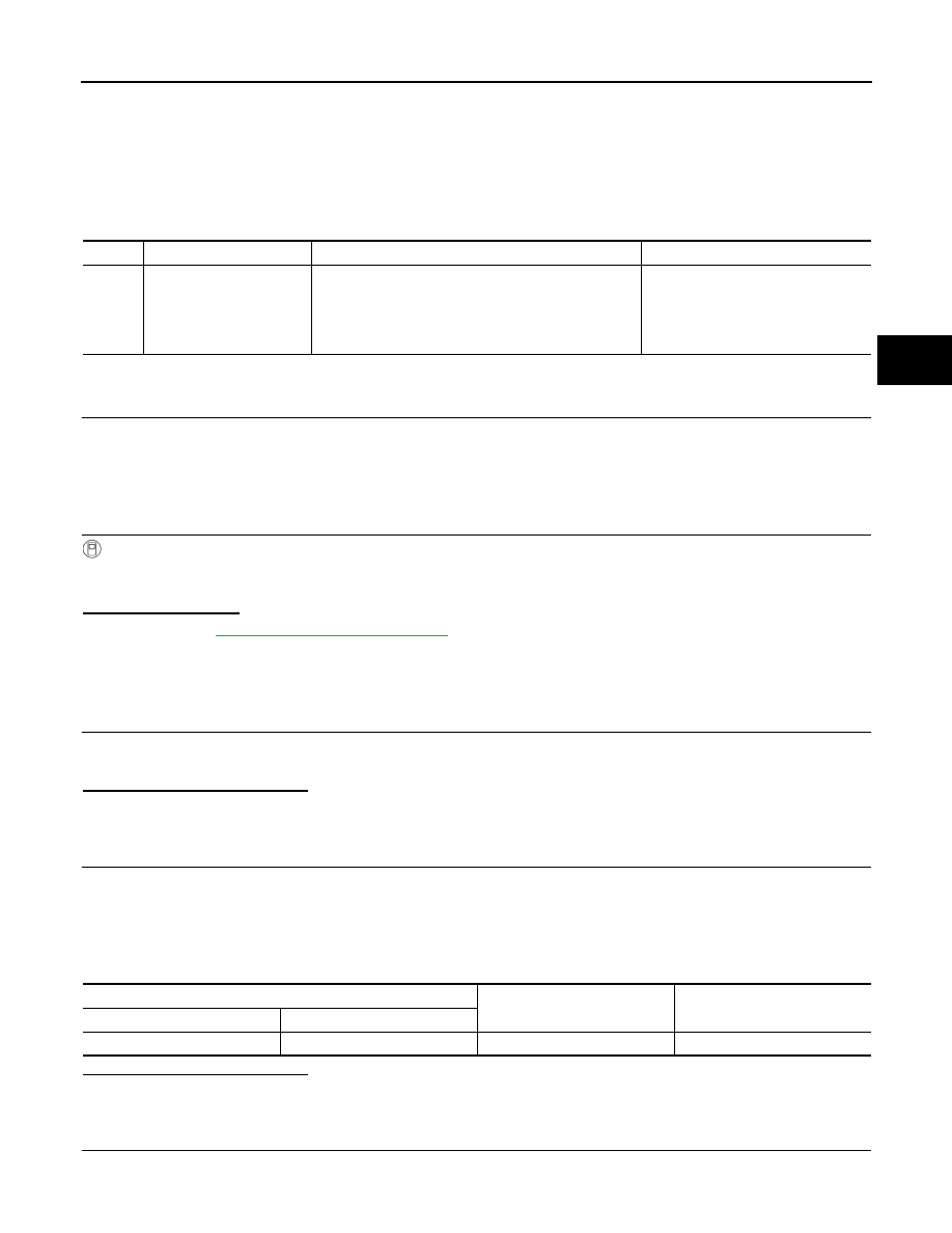
DTC
Display itemI
Malfunction detected condition
Possible cause
C1801
VHCL HEIGHT SENSOR
Signal voltage of the vehicle height sensor remains 0.2
V or less or 4.6 V or more continuously for 60 seconds
during sensor voltage (4.5 – 5.5 V) output by the air lev-
elizer control module.
• Harness or connectors
(Sensor circuit is open.)
• Vehicle height sensor
• Air levelizer control module
• Rear suspension component parts
Vehicle height sensor
—
Voltage
Connector Terminal
C13
1
Ground
4.5 – 5.5 V