Content .. 1073 1074 1075 1076 ..
Infiniti QX56 (Z62). Manual - part 1075
SB-22
< REMOVAL AND INSTALLATION >
LATCH SYSTEM FOR CHILDREN
LATCH SYSTEM FOR CHILDREN
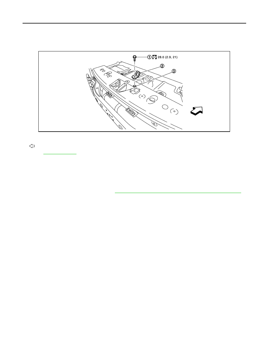
Exploded View
INFOID:0000000006217633
Removal and Installation
INFOID:0000000006217634
REMOVAL
CAUTION:
Replace anchor bolts if they are deformed or worn out.
1.
Remove the luggage rear plate. Refer to
INT-35, "LUGGAGE REAR PLATE : Removal and Installation"
2.
Remove anchor bolt, and then remove LATCH (Lower Anchor and Tether for Children) system.
INSTALLATION
Install in the reverse order of removal.
1.
Anchor bolt
2.
Anchor plate
3.
Retaining washer
: Vehicle front
Refer to
for symbols in the figure.
JMHIA1484GB