Infiniti QX56 (Z62). Manual - part 84
AV-190
< DTC/CIRCUIT DIAGNOSIS >
SIDE CAMERA RH COMMUNICATION SIGNAL CIRCUIT
SIDE CAMERA RH COMMUNICATION SIGNAL CIRCUIT
Description
INFOID:0000000006216362
• Around view monitor control unit supplies to the front camera, rear camera and side camera. And then it
superimpose the images from each camera and outputs then to the front display unit.
• Superimpose the guiding lines, predictive course line and sonar indicator to the camera image that outputs
to the front display unit.
• Around view monitor control unit performs the reception/transmission of communication signal with each
camera.
Diagnosis Procedure
INFOID:0000000006216363
1.
CHECK CONTINUITY COMMUNICATION SIGNAL CIRCUIT
1.
Turn ignition switch OFF.
2.
Disconnect around view monitor control unit connector and door mirror (passenger side) connector.
3.
Check continuity between around view monitor control unit harness connector and door mirror (passenger
side) harness connector.
4.
Check continuity between around view monitor control unit harness connector and ground.
Is inspection result normal?
YES
>> GO TO 2.
NO
>> Repair harness or connector.
2.
CHECK COMMUNICATION SIGNAL
1.
Connect around view monitor control unit connector and door mirror (passenger side) connector.
2.
Turn ignition switch ON.
3.
Check signal between around view monitor control unit harness connector and ground.
Is inspection result normal?
YES
>> Replace around view monitor control unit. Refer to
AV-233, "Removal and Installation"
NO
>> Replace side camera RH. Refer to
AV-236, "Removal and Installation"
Around view monitor control
unit
Door mirror
(passenger side)
Continuity
Connector
Terminal
Connector
Terminal
M48
33
D23
3
Existed
Around view monitor control
unit
Ground
Continuity
Connector
Terminal
M48
33
Not existed
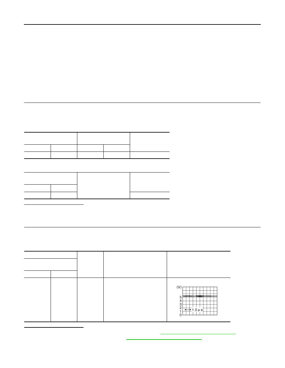
(+)
(
−
)
Condition
Reference value
Around view monitor control
unit
Connector
Terminal
M48
33
Ground
“CAMERA” switch is ON or shift
position is “R”.
JSNIA0836GB