Infiniti QX56 (Z62). Manual - part 50
AV-54
< ECU DIAGNOSIS INFORMATION >
AV CONTROL UNIT
68
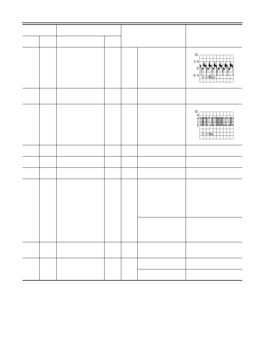
(R)
Ground
Composite image signal
Output
Ignition
switch
ON
At DVD image is displayed.
72
(Y/G)
Ground
Microphone VCC
Output
Ignition
switch
ON
—
5.0 V
73
(Y/G)
Ground
Communication signal
(CONT
→
DISP)
Output
Ignition
switch
ON
When adjusting display
brightness.
74
(P)
—
CAN–L
Input/
Output
—
—
—
75
(LG)
—
AV communication signal
(L)
Input/
Output
—
—
—
76
(LG)
—
AV communication signal
(L)
Input/
Output
—
—
—
79
(L/O)
Ground
Dimmer signal
Input
Ignition
switch
ON
Either of the following con-
ditions
• Lighting switch is OFF
• Lighting switch is 1st or
2nd, and the area around
the vehicle is bright
(shine a light on the opti-
cal sensor)
0 V
Lighting switch is 1st or
2nd, and the area around
the vehicle is dark (block
the light from the optical
sensor)
12.0 V
80
(GR/L)
Ground
Ignition signal
Input
Ignition
switch
ON
—
Battery voltage
81
(R/Y)
Ground
Reverse signal
Input
Ignition
switch
ON
Selector lever is in R posi-
tion.
12.0 V
Selector lever is in other
than R position.
0 V
Terminal
(Wire color)
Description
Condition
Reference value
(Approx.)
+
–
Signal name
Input/
Output
SKIB2251J
PKIB5039J