Infiniti QX56 (Z62). Manual - part 45


  Index      Infiniti     Infiniti QX56 (Z62) - service repair manual 2011 year


Search            


Content   ..  43  44  45  46   ..


Infiniti QX56 (Z62). Manual - part 45


AV-34

< SYSTEM DESCRIPTION >

DIAGNOSIS SYSTEM (AV CONTROL UNIT)

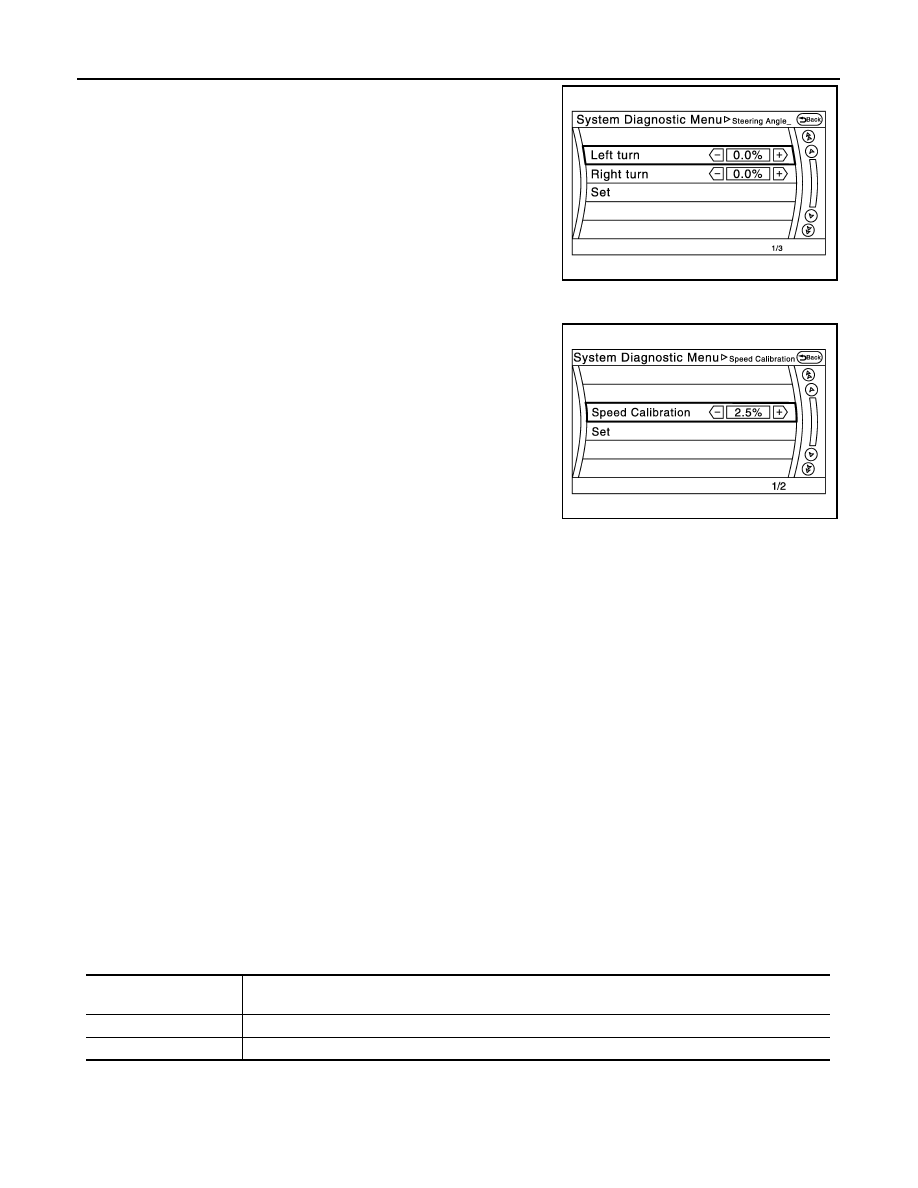
The steering angle output value detected with the gyroscope is
adjusted.

SPEED CALIBRATION
During normal driving, distance error caused by tire wear and tire
pressure change is automatically adjusted for by the automatic dis-
tance correction function. This function, on the other hand, is for
immediate adjustment, in cases such as driving with tire chain fitted
on tires.

Error History

The self-diagnosis results are judged depending on whether any error occurs from when “Self-diagnosis” is
selected until the self-diagnosis results are displayed.
However, the diagnosis results are judged normal if an error has occurred before the ignition switch is turned
ON and then no error has occurred until the self-diagnosis start. Check the “Error Record” to detect any error
that may have occurred before the self-diagnosis start because of this situation.
The error record displays the time and place of the most recent occurrence of that error. However, take note of
the following points.
• If there is a malfunction with the GPS antenna circuit board in the AV control unit, the correct date and time

of occurrence may not be able to be displayed.

• Place of the error occurrence is represented by the position of the current location mark at the time an error

occurred. If current location mark has deviated from the correct position, then the place of the error occur-
rence cannot be located correctly.

• The frequency of occurrence is displayed in a count up manner. The actual count up method differs depend-

ing on the error item. 

Count up method A
• The counter resets to 0 if an error occurs when ignition switch is turned ON. The counter increases by 1 if

the condition is normal at a next ignition ON cycle. 

• The counter upper limit is 39. Any counts exceeding 39 are ignored.“ The counter can be reset (no error

record display) with the “Delete log” switch or CONSULT-III.

Count up method B
• The counter increases by 1 if an error occurs when ignition switch is ON. The counter will not decrease even

if the condition is normal at the next ignition ON cycle. 

• The counter upper limit is 50. Any counts exceeding 50 are ignored. “ The counter can be reset (no error

record display) with the “Delete log” switch or CONSULT-III.

JSNIA2179ZZ

JSNIA2180ZZ

Display type of occur-

rence frequency

Error history display item

Count up method A

CAN communication line, control unit (CAN), AV communication line, control unit (AV)

Count up method B

Other than the above

AV

DIAGNOSIS SYSTEM (AV CONTROL UNIT)

AV-35

< SYSTEM DESCRIPTION >

C

D

E

F

G

H

I

J

K

L

M

B

A

O

P

Error item
Some error items may be displayed simultaneously according to the cause. If some error items are displayed
simultaneously, the detection of the cause can be performed by the combination of display items

JPNIA1788GB

Error item

Description

Possible malfunction factor/Action to take

CAN COMM CIRCUIT

CAN communication malfunction is detect-
ed.

Perform diagnosis with CONSULT-III, and 
then repair the malfunctioning parts accord-
ing to the diagnosis results.
Refer to 

AV-39, "CONSULT-III Function"

.

CONTROL UNIT (CAN)

CAN initial diagnosis malfunction is detect-
ed.

Replace the AV control unit if the malfunc-
tion occurs constantly.
Refer to 

AV-212, "Removal and Installa-

tion"

.

CONTROL UNIT (AV)

AV communication circuit initial diagnosis 
malfunction is detected.

FLASH-ROM Error Of Control Unit

AV control unit malfunction is detected.

Connection Of Gyro

Connection of G Sensor

CAN Controller Memory Error

Bluetooth Module Connection Error

Sub CPU Connection Error

Audio connection error

DSP Connection Error

AV control unit malfunction is detected.

• If a disc can be played, then there is a 

possibility of the detection of a temporary 
malfunction.

• Replace the AV control unit if the mal-

function occurs constantly.
Refer to 

AV-212, "Removal and Installa-

tion"

.

DSP Communication Error

HDD Connection Error

AV control unit malfunction is detected.

• If the music box function has no malfunc-

tions, then there is a possibility of the de-
tection of a temporary malfunction.

• Replace the AV control unit if the mal-

function occurs constantly.
Refer to 

AV-212, "Removal and Installa-

tion"

.

HDD Read Error

HDD Write Error

HDD Communication Error

HDD Access Error

GPS Communication Error

GPS malfunction is detected.

• An intermittent error caused by strong ra-

dio interference may be detected unless 
any symptom (GPS reception error, etc.) 
occurs.

• Replace the AV control unit if the mal-

function occurs constantly.
Refer to 

AV-212, "Removal and Installa-

tion"

.

GPS ROM Error

GPS RAM Error

GPS RTC Error

AV-36

< SYSTEM DESCRIPTION >

DIAGNOSIS SYSTEM (AV CONTROL UNIT)

Unfinished configuration

The writing of configuration data is incom-
plete.

Write configuration data with CONSULT-III.

USB Controller Communication Error

USB connection malfunction is detected.

Check that the connection to the USB con-
nector is normal.

DVD Mechanism Communication Error

AV control unit malfunction is detected.

• If DVD can be played, then there is a 

possibility of the detection of a temporary 
malfunction.

• Replace the AV control unit if the mal-

function occurs constantly.
Refer to 

AV-212, "Removal and Installa-

tion"

.

Steer. Angle Sensor Calibration

Predictive course line center position ad-
justment of the steering angle sensor is in-
complete.

Adjust the predictive course line center po-
sition of the steering angle sensor.
Refer to 

AV-39, "CONSULT-III Function"

.

Front Display Connection Error

When either one of the following items are 
detected:
• front display unit power supply and 

ground circuits are malfunctioning.

• Serial communication circuits between 

AV control unit and front display unit are 
malfunctioning.

• Front display unit power supply and 

ground circuits.

• Serial communication circuits between 

AV control unit and front display unit.

• AV COMM CIRCUIT
• 2nd Display Connection Error

When either one of the following items are 
detected:
• video distributor power supply and 

ground circuits are malfunctioning.

• headrest display unit LH power supply 

and ground circuits are malfunctioning.

• AV communication circuits between AV 

control unit and headrest display unit LH 
are malfunctioning.

• location recognition signal circuit be-

tween headrest display unit LH and 
ground is malfunctioning.

• Video distributor power supply and 

ground circuits.

• Headrest display unit LH power supply 

and ground circuits.

• AV communication circuits between AV 

control unit and headrest display unit LH.

• Location recognition signal circuit be-

tween headrest display unit LH and 
ground.

3rd Display Connection Error

When either one of the following items are 
detected:
• headrest display unit RH power supply 

and ground circuits are malfunctioning.

• AV communication circuits between 

headrest display unit LH and headrest 
display unit RH are malfunctioning.

• location recognition signal circuit be-

tween headrest display unit RH and 
ground is malfunctioning.

• Headrest display unit RH power supply 

and ground circuits.

• AV communication circuits between 

headrest display unit LH and headrest 
display unit RH.

• Location recognition signal circuit be-

tween headrest display unit RH and 
ground.

AM/FM antenna amplifier short to ground

Radio antenna amp. ON signal circuit mal-
function is detected.

Radio antenna amp. ON signal circuit  be-
tween AV control unit and antenna amp.

AM/FM antenna amplifier open

Ext_Amp_ON output terminal short to 
ground

BOSE amp. ON signal circuit malfunction is 
detected.

BOSE amp. ON signal circuit  between AV 
control unit and BOSE amp.

Ext_Amp_ON output terminal :open

GPS Antenna Error

GPS antenna connection malfunction is de-
tected.

Check the connection of the GPS antenna 
connector.

XM Antenna Connection Error

Satellite radio antenna connection malfunc-
tion is detected.

Satellite radio antenna disconnection.

USB electric current Error

Detection of overcurrent in USB connector.

Check USB harness between the AV con-
trol unit and USB connector. 

Error item

Description

Possible malfunction factor/Action to take

AV

DIAGNOSIS SYSTEM (AV CONTROL UNIT)

AV-37

< SYSTEM DESCRIPTION >

C

D

E

F

G

H

I

J

K

L

M

B

A

O

P

Vehicle CAN Diagnosis

• CAN communication status and error counter is displayed.
• The error counter displays “OK” if any malfunction was not

detected in the past and displays “0” if a malfunction is detected. It
increases by 1 if the condition is normal at the next ignition switch
ON cycle. The upper limit of the counter is 39.

• The error counter is erased if “Reset” is pressed.

NOTE:
“???” indicates UNKWN.

AV COMM Diagnosis

• AV COMM CIRCUIT
• Switches Connection Error

When either one of the following items are 
detected:
• multifunction switch power supply and 

ground circuits were malfunctioning.

• AV communication circuits between AV 

control unit and multifunction switch are 
malfunctioning.

• Multifunction switch power supply and 

ground circuits.

• AV communication circuits between AV 

control unit and multifunction switch.

• AV COMM CIRCUIT
• AVM Connection Error

When either one of the following items are 
detected:
• around view monitor control unit power 

supply and ground circuits are malfunc-
tioning.

• AV communication circuits between AV 

control unit and around view monitor 
control unit are malfunctioning.

• Around view monitor control unit power 

supply and ground circuits.

• AV communication circuits between AV 

control unit and around view monitor 
control unit.

• AV COMM CIRCUIT
• Sonar Connection Error

When either one of the following items are 
detected:
• sonar control unit power supply and 

ground circuits are malfunctioning.

• AV communication circuits between AV 

control unit and sonar control unit are 
malfunctioning.

• Sonar control unit power supply and 

ground circuits.

• AV communication circuits between AV 

control unit and sonar control unit.

• AV COMM CIRCUIT
• Switches Connection Error
• Sonar Connection Error
• AVM Connection Error

AV communication circuits between AV 
control unit and multifunction switch are 
malfunctioning.

AV communication circuits between AV 
control unit and multifunction switch.

• AV COMM CIRCUIT
• Switches Connection Error
• Sonar Connection Error
• AVM Connection Error
• 2nd Display Connection Error

Error item

Description

Possible malfunction factor/Action to take

Items

Display (Current)

Malfunction counter

(Past)

Tx(HVAC)

OK / ???

OK / 0 – 39

Rx(ECM)

OK / ???

OK / 0 – 39

Rx(Cluster)

OK / ???

OK / 0 – 39

Rx(HVAC)

OK / ???

OK / 0 – 39

Rx(USM)

OK / ???

OK / 0 – 39

Rx(TPMS)

OK / ???

OK / 0 – 39

Rx(STRG)

OK / ???

OK / 0 – 39

Rx(ACC)

OK / ???

OK / 0 – 39

RX(VDC)

OK / ???

OK / 0 – 39

JSNIA2391ZZ


Content   ..  43  44  45  46   ..