Infiniti QX56 (Z62). Manual - part 44


  Index      Infiniti     Infiniti QX56 (Z62) - service repair manual 2011 year


Search            


Content   ..  42  43  44  45   ..


Infiniti QX56 (Z62). Manual - part 44


AV-30

< SYSTEM DESCRIPTION >

DIAGNOSIS SYSTEM (AV CONTROL UNIT)

4.

Items of “Self Diagnosis” and “Confirmation/Adjustment” can be
selected on the trouble diagnosis initial screen.
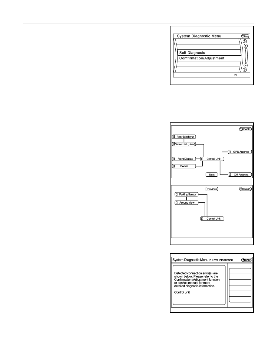
SELF-DIAGNOSIS MODE

1.

Start the self-diagnosis function and select “Self Diagnosis”.

-

Self-diagnosis subdivision screen is displayed, and the self-diagnosis mode starts.

-

The bar graph visible on the center of the self-diagnosis subdivision screen indicates progress of the trou-
ble diagnosis.

2.

Diagnosis results are displayed after the self-diagnosis is com-
pleted. The unit names and the connection lines are color-coded
according to the diagnostic results.

NOTE:

Control unit (AV control unit) is displayed in red.

• Replace AV control unit if “Self-Diagnosis did not run because of a control

unit malfunction” is indicated. The symptom is AV control unit internal error.
Refer to 

AV-212, "Removal and Installation"

.

• If multiple errors occur at the same time for a single unit, the screen switch

colors are determined according to the following order of priority: red > gray.

-

The comments of the self-diagnosis results can be viewed with a
component in the diagnosis result screen.

Detection Range of Self-diagnosis Mode

• The self-diagnosis mode allows the technician to diagnose the connection in the communication line

between AV control unit and each unit and the internal operation of the AV control unit.

• Because the start condition of diagnosis function is a switch operation, the on board diagnosis function can-

not be started up if any malfunction is detected in the communication circuit between AV control unit and
multifunction switch.

JSNIA2173ZZ

Diagnosis results

Unit

Connec-

tion line

Normal

Green

Green

Connection malfunction

Gray

Yellow

Unit malfunction 

Note

Red

Green

JSNIA3191ZZ

JPNIA1787ZZ

AV

DIAGNOSIS SYSTEM (AV CONTROL UNIT)

AV-31

< SYSTEM DESCRIPTION >

C

D

E

F

G

H

I

J

K

L

M

B

A

O

P

SELF-DIAGNOSIS RESULTS

Check the applicable display at the following table, and then repair the malfunctioning parts.

Only Unit Part Is Displayed In Red.

A Connecting Cable Between Units Is Displayed In Yellow.

CONFIRMATION/ADJUSTMENT MODE

Screen switch

Description

Possible malfunction location / Action to 

take

Control Unit

Malfunction is detected in AV control unit 
power supply and ground circuits.

Check AV control unit power supply and 
ground circuits. When detecting no mal-
function in those components, replace AV 
control unit.

Area with yellow connection lines

Description

Possible malfunction location / Action to 

take

Control unit 

 Front Display

Serial communication circuits between AV 
control unit and front display unit are mal-
functioning.

Serial communication circuits between AV 
control unit and front display unit.

Control unit 

 GPS Antenna

GPS antenna connection malfunctions de-
tected.

Check the connection of the GPS antenna 
connector.

Control unit 

 XM Antenna

Satellite radio antenna connection malfunc-
tion is detected.

Satellite radio antenna disconnection

Control unit 

 Around view

Around view 

 Parking Sensor

When either one of the following items are 
detected:
• around view monitor control unit power 

supply and ground circuits are malfunc-
tioning.

• AV communication circuits between AV 

control unit and around view monitor 
control unit are malfunctioning.

• Around view monitor control unit power 

supply and ground circuits.

• AV communication circuits between AV 

control unit and around view monitor 
control unit.

Control unit 

 Parking Sensor

Around view 

 Parking Sensor

When either one of the following items are 
detected:
• sonar control unit power supply and 

ground circuits are malfunctioning.

• AV communication circuits between AV 

control unit and sonar control unit are 
malfunctioning.

• Sonar control unit power supply and 

ground circuits.

• AV communication circuits between AV 

control unit and sonar control unit.

Control unit 

 Video Dist.(Rear)

Video Dist.(Rear) 

 Rear display 2

When either one of the following items are 
detected:
• video distributor power supply and 

ground circuits are malfunctioning.

• headrest display unit LH power supply 

and ground circuits are malfunctioning.

• AV communication circuits between AV 

control unit and headrest display unit LH 
are malfunctioning.

• location recognition signal circuit be-

tween headrest display unit LH and 
ground is malfunctioning.

• Video distributor power supply and 

ground circuits.

• Headrest display unit LH power supply 

and ground circuits.

• AV communication circuits between AV 

control unit and headrest display unit LH.

• Location recognition signal circuit be-

tween headrest display unit LH and 
ground.

Video Dist.(Rear) 

 Rear display 2

When either one of the following items are 
detected:
• headrest display unit RH power supply 

and ground circuits are malfunctioning.

• AV communication circuits between 

headrest display unit LH and headrest 
display unit RH are malfunctioning.

• location recognition signal circuit be-

tween headrest display unit RH and 
ground is malfunctioning.

• Headrest display unit RH power supply 

and ground circuits.

• AV communication circuits between 

headrest display unit LH and headrest 
display unit RH.

• Location recognition signal circuit be-

tween headrest display unit RH and 
ground.

AV-32

< SYSTEM DESCRIPTION >

DIAGNOSIS SYSTEM (AV CONTROL UNIT)

1.

Start the diagnosis function and select “Confirmation/Adjustment”. The confirmation/adjustment mode
indicates where each item can be checked or adjusted.

2.

Select each switch on the “Confirmation/Adjustment Mode”
screen to display the relevant trouble diagnosis screen. Press
the “Back” switch to return to the initial Confirmation/Adjustment
Mode screen.

Display Diagnosis

Vehicle Signals

JSNIA2990ZZ

JSNIA2176GB

AV

DIAGNOSIS SYSTEM (AV CONTROL UNIT)

AV-33

< SYSTEM DESCRIPTION >

C

D

E

F

G

H

I

J

K

L

M

B

A

O

P

A comparison check can be made of each actual vehicle signal and
the signals recognized by the system.

Speaker Test

Select “SPEAKER DIAGNOSIS” to display the Speaker Diagnosis
screen. Press “Start” to generate a test tone in a speaker. Press
“Start” to generate a test tone in the next speaker. Press “Stop” to
stop the test tones.

Navigation

STEERING ANGLE ADJUSTMENT

JSNIA2991ZZ

Diagnosis item

Display

Vehicle status

Remarks

Vehicle speed

ON

Vehicle speed >= 8 km/h (5 MPH)

Changes in indication may be delayed. This is normal.

OFF

Vehicle speed < 8 km/h (5 MPH)

Parking brake

ON

Parking brake is applied.

OFF

Parking brake is released.

Lights

ON

Block the light from the auto light 
optical sensor when the lighting 
switch is 1st or 2nd.

OFF

Either of the following conditions.
• Lighting switch is OFF
• Expose the auto light optical sen-

sor to light when the lighting 
switch is 1st or 2nd.

Ignition

ON

Ignition switch is ON.

OFF

Ignition switch is in ACC position.

Reverse

ON

Selector lever is in “R” position.

Changes in indication may be delayed. This is normal.

OFF

Selector lever is in other than “R” 
position.

Side view Switch

OFF

This item is displayed, but cannot be monitored.

Room Lamp

OFF

This item is displayed, but cannot be monitored.

JPNIA1828ZZ


Content   ..  42  43  44  45   ..