Infiniti Q45. Manual - part 916


  Index      Infiniti     Infiniti Q45 - service repair manual 2006 year


Search            copyright infringement  


Content   ..  914  915  916  917   ..


Infiniti Q45. Manual - part 916


FRONT WIPER AND WASHER SYSTEM (WITH RAIN SENSOR)

WW-17

C

D

E

F

G

H

I

J

L

M

A

B

WW

On Board Diagnosis

NKS001FB

IVMS can check communication diagnosis, switch monitor, and central locking system self diagnosis
using on board diagnosis.

Map lamps and step lamps (all seats) act as the indicators for on board diagnosis.

DIAGNOSIS ITEM 

SWITCH MONITOR

Performs diagnosis on the switch system to each control unit.

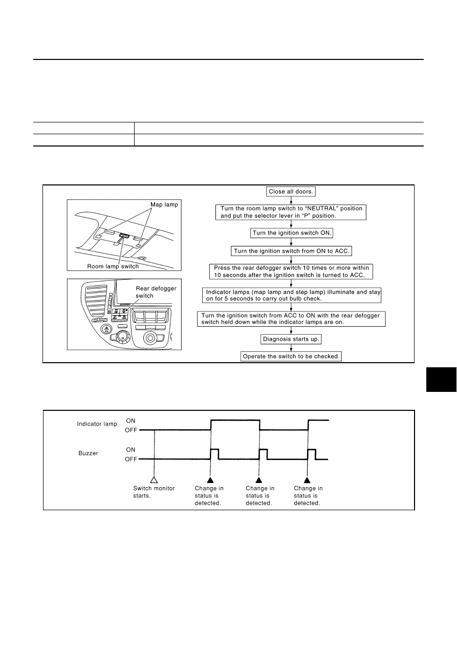
How to Perform Switch Monitor

Description

Detects the status change (switch ON/OFF operation) of switch to be checked, and turns ON/OFF indica-
tor lamps (the map lamp and step lamp). Also sounds the buzzer for 0.5 seconds.

If a malfunction is detected, no indicator lamp and buzzer react.

Diagnosis item

Description

Switch monitor

Checks for malfunction in switch systems that input to BCM and each LCU.

PKIA7882E

PIIA0177E

WW-18

FRONT WIPER AND WASHER SYSTEM (WITH RAIN SENSOR)

Switch Monitor Item

The status of the switch (except the ignition switch, interior lamp illumination switch, and map lamp switch)
as input to each control unit can be monitored.

Switch Monitor Cancellation 

Either or both the following conditions are satisfied, the communication diagnosis is cancelled.

Turn ignition switch OFF.

Drive vehicle more at speed higher than 7 km/h (4 MPH).

Control unit

Item

BCM

Wiper and washer switch

FRONT WIPER AND WASHER SYSTEM (WITH RAIN SENSOR)

WW-19

C

D

E

F

G

H

I

J

L

M

A

B

WW

Front Wiper Operates by Itself in Fine Weather

NKS001FC

1. 

CHECK CONDITIONS OF WINDSHIELD (RAIN SENSOR DETECTION AREA)

Check rain sensor detection area of windshield for dirt such as greases.
OK or NG

OK

>> GO TO 2.

NG

>> Clean rain sensor detection area of windshield fully.

2. 

CHECK RAIN SENSOR OUTPUT SIGNAL

With CONSULT-II

1.

Select “IVMS” on CONSULT-II. And select “WIPER” on “SELECT TEST ITEM” screen.

2.

Select “DATA MONITOR” on “SELECT DIAG MODE” screen.

3.

Make sure that “RAIN SENSOR” of “DATA MONITOR” is 87 %
with no water drops in sensor detection area.

Without CONSULT-II

With no water drops in sensor detection area, check voltage waveform between BCM harness connector R4
terminal 134 and ground when wiper stops.

OK or NG

OK

>> Replace BCM.

NG

>> GO TO 3.

3. 

CHECK RAIN SENSOR OUTPUT SIGNAL CIRCUIT

1.

Turn ignition switch OFF.

2.

Disconnect BCM connector and rain sensor connector.

3.

Check continuity between rain sensor harness connector R20
terminal 2 and BCM harness connector R4 terminal 134. 

4.

Check continuity between rain sensor harness connector R20
terminal 2 and ground.

OK or NG

OK

>> GO TO 4.

NG

>> Check harness for open or short between rain sensor and BCM.

PKIA9814E

134 - Ground

: Refer to 

WW-13, "Terminals and Reference Values for BCM"

 .

2 - 134

: Continuity should exist.

2 - Ground

: Continuity should not exist.

PKIA9819E

WW-20

FRONT WIPER AND WASHER SYSTEM (WITH RAIN SENSOR)

4. 

CHECK RAIN SENSOR POWER SUPPLY

1.

Turn ignition switch ON.

2.

Check voltage between rain sensor harness connector R20 ter-
minal 1 and ground.

OK or NG

OK

>> GO TO 5.

NG

>> Check harness for open or short between rain sensor

and fuse.

5. 

CHECK RAIN SENSOR GROUND CIRCUIT

1.

Turn ignition switch OFF.

2.

Check continuity between rain sensor harness connector R20
terminal 3 and ground.

OK or NG

OK

>> Replace rain sensor.

NG

>> Check harness ground circuit.

1 - Ground

: Battery voltage

PKIA9815E

3 - Ground

: Continuity should exist.

PKIA9816E


Content   ..  914  915  916  917   ..