Infiniti Q45. Manual - part 915


  Index      Infiniti     Infiniti Q45 - service repair manual 2006 year


Search            copyright infringement  


Content   ..  913  914  915  916   ..


Infiniti Q45. Manual - part 915


FRONT WIPER AND WASHER SYSTEM (WITH RAIN SENSOR)

WW-13

C

D

E

F

G

H

I

J

L

M

A

B

WW

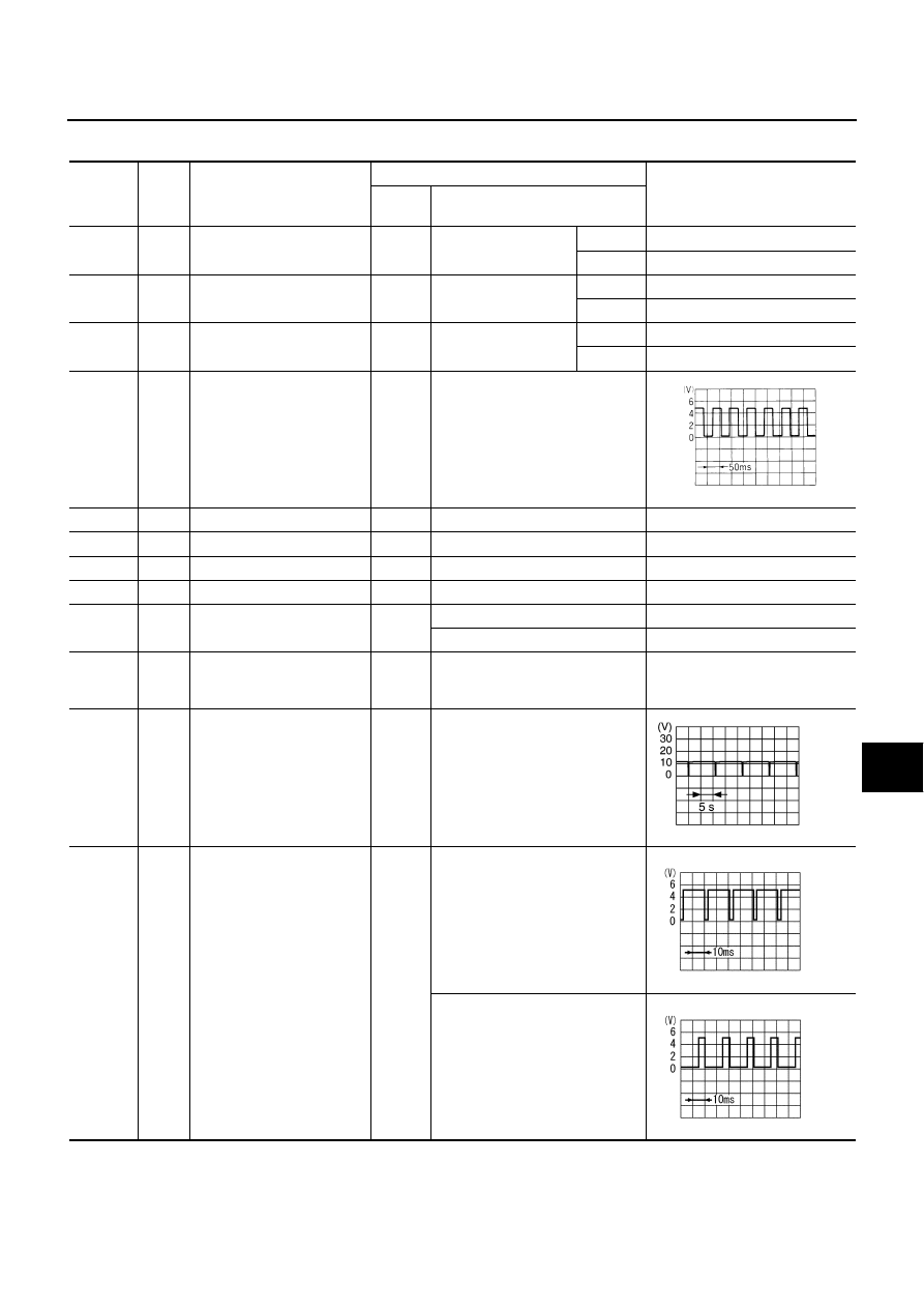
Terminals and Reference Values for BCM

NKS001F7

Terminal 

No.

Wire 

color

Item

 Condition

Reference value

Ignition 

switch

 Operation or condition

4

P

Front washer switch signal

ON

Front washer switch

ON

Approx. 0 V

OFF

Battery voltage

9

OR

Front wiper switch INT signal

ON

Front wiper switch

INT

Approx. 0 V

OFF

Approx. 8 V

48

GY/L

Intermittent wiper volume 
signal

ON

Wiper intermittent 
interval

Long

Approx. 3.6 V

Short

Approx. 0 V

49

P/L

Vehicle speed signal
(2-pulse)

ON

Vehicle speed approx. 40 km/h
(25 MPH)

56

B

Ground

ON

Approx. 0 V

68

W/B

Ignition switch (ON)

ON

Battery voltage

105

Y/L

Battery power supply

OFF

Battery voltage

113

B

Ground

ON

Approx. 0 V

124

SB

Front wiper auto
stop signal

ON

Front wiper is moving.

Approx. 0 V

Front wiper is stopped.

Battery voltage

126

L

Front wiper HI signal

ON

Front wiper switch: INT position 
(HI operation when water is sprin-
kled on rain sensor) 

Approx. 0 V

128

R/Y

Front wiper motor
operation signal

ON

Front wiper switch: INT position
(Wiper dial position 4)

134

B/R

Rain sensor signal

ON

Front wiper switch: INT position 
(Front wiper is stopped.)

Front wiper switch: INT position 
(Wiper is moving when water is 
sprinkled on rain sensor.)

ELF1080D

PKIA6250E

SKIA0207J

SKIA0208J

WW-14

FRONT WIPER AND WASHER SYSTEM (WITH RAIN SENSOR)

Work Flow

NKS001F8

1.

Confirm the symptom or customer complaint.

2.

Understand the system description. Refer to 

WW-4, "System Description"

 .

3.

Perform Preliminary Check. Refer to 

WW-14, "Preliminary Check"

 .

4.

According to the trouble diagnosis chart, repair or replace the cause of the malfunction.

5.

Does wiper function operate normally? If YES: GO TO 6. If NO: GO TO 4.

6.

INSPECTION END

Preliminary Check

NKS001F9

CHECK POWER SUPPLY AND GROUND CIRCUIT

1. 

CHECK FUSE

Check for blown fuses.

Refer to 

WW-9, "Wiring Diagram — WIPER —"

 .

OK or NG

OK

>> GO TO 2.

NG

>> If fuse is blown, be sure to eliminate cause of malfunction before installing new fuse. Refer to 

PG-

2, "POWER SUPPLY ROUTING"

 .

2. 

CHECK POWER SUPPLY CIRCUIT

1.

Disconnect BCM connector.

2.

Check voltage between BCM harness connector and ground.

OK or NG

OK

>> GO TO 3.

NG

>> Repair harness or connector.

3. 

CHECK GROUND CIRCUIT

1.

Turn ignition switch OFF.

2.

Check continuity between BCM harness connector and ground.

OK or NG

OK

>> INSPECTION END

NG

>> Repair harness or connector.

Unit

Power source

Fuse No.

BCM

Battery

3

Ignition switch ON or START 

1

Terminal

Ignition switch position

(+)

(

)

OFF

ON

Connector

Terminal 

M4

105

Ground

Battery voltage

Battery voltage

68

Approx. 0 V

Battery voltage

PKIB1712E

Terminal

Continuity

Connector

Terminal

Ground

M4

56

Yes

113

PKIA5168E

FRONT WIPER AND WASHER SYSTEM (WITH RAIN SENSOR)

WW-15

C

D

E

F

G

H

I

J

L

M

A

B

WW

CONSULT-II Function (IVMS)

NKS001FA

CONSULT-II can display each diagnostic item using the diagnostic test mode shown following.

CONSULT-II BASIC OPERATION 

CAUTION:

If CONSULT-II is used with no connection of CONSULT-II CONVERTER, malfunctions might be
detected in self-diagnosis depending on control unit which perform CAN communication.

1.

With ignition switch OFF, connect “CONSULT-II” and “CON-
SULT-II CONVERTER” to data link connector, and turn ignition
switch ON.

2.

Select “START (NISSAN BASED VHCL)”.

3.

Select “IVMS”.
If “IVMS” is not indicated, refer to 

GI-37, "CONSULT-II Data Link

Connector (DLC) Circuit"

 .

IVMS diagnosis part

Diagnosis mode

Description

WIPER

DATA MONITOR

Displays data relative to BCM input signals and various control related data 
for each system.

ACTIVE TEST

Device operation can be checked by applying a drive signal to device.

BCM PART NUMBER

Displays BCM part number.

PKIB0601E

BCIA0029E

BCIA0030E

WW-16

FRONT WIPER AND WASHER SYSTEM (WITH RAIN SENSOR)

4.

Select “WITH SUNROOF” on “SELECT SYS COND” screen.

5.

Touch “OK”. If the selection is wrong, touch “CANCEL”.

6.

Select the desired part to be diagnosed on “SELECT TEST
ITEM” screen.

DATA MONITOR 
Operation Procedure

1.

Select “WIPER” on “SELECT TEST ITEM” screen

2.

Select “DATA MONITOR” on “SELECT DIAG MODE” screen.

3.

Select either “ALL SIGNALS” or “SELECTION FROM MENU” on “DATA MONITOR” screen.

4.

When “SELECTION FROM MENU” is selected, touch items to be monitored. If “ALL SINGNALS” is
selected, all items will be monitored.

5.

Touch “START”.

6.

Touch “RECORDING START” while monitoring to record the status of the item being monitored. To stop
recording, touch “RECORDING STOP”.

Data Monitor Item

ACTIVE TEST 
Operation Procedure

1.

Select “WIPER” on “SELECT TEST ITEM” screen.

2.

Select “ACTIVE TEST” on “SELECT DIAG MODE” screen.

3.

Select the item to be tested, and check the operation.

4.

During the operation check, touching “OFF” deactivates the operation.

PIIA0184E

ALL SIGNALS

Monitors all the signals.

SELECTION FROM MENU

Selects items and monitors them.

Monitored item

Contents

IGN ON SW

Indicates “IGN [ON] / ACC or OFF [OFF]” condition of ignition switch signal.

INT SW

Indicates “ INT position [ON] / Others [OFF]” condition of front wiper switch signal.

WASH SW

Indicates “WASH position [ON] / Others [OFF]” condition of front wiper switch signal.

VHCL SPEED SE

Indicates “Vehicle is running [RUN] / Vehicle stopped [STOP]” condition of vehicle speed signal.

WIPR AUTO STP

Indicates “INT or OFF position [IGN] / LO or HI position [OFF]” condition of front wiper switch signal.

INT RESIST

Indicates “ Intermittent resistance value [approx. 0 to 1 kohm]” condition of front wiper switch signal.

RAIN SENSOR

Output value of rain sensor is displayed on the duty ratio.

Test item

Front wiper motor operation

 WIPER AMP

ON

Operate (LO)

OFF

Stop

WIPER MOTOR (HI)

ON

Operate (HI)

OFF

Stop


Content   ..  913  914  915  916   ..